This Section covers structural design (principles) of all building foundations such as raft, pile and other foundation systems to ensure safety and serviceability without exceeding the permissible stresses of the materials of foundations and the bearing capacity of the supporting soil.
2Terminology
2.0 For the purpose of this Section, the following definitions shall apply.
2.1 General
2.1.1 Clay — An aggregate of microscopic and sub-microscopic particles derived from the chemical decomposition and disintegration of rock constituents. It is plastic within a moderate to wide range of water content. The particles are less than 0.002 mm in size.
2.1.2 Clay, Firm — A clay which at its natural water content can be moulded by substantial pressure with the fingers and can be excavated with a spade.
2.1.3 Clay, Soft — A clay which at its natural water content can be easily moulded with the fingers and readily excavated.
2.1.4 Clay, Stiff — A clay which at its natural water content cannot be moulded with the fingers and requires a pick or pneumatic spade for its removal.
2.1.5 Foundation — That part of the structure which is in direct contact with and transmits loads to the ground.
2.1.6 Gravel — Cohesionless aggregates of angular rounded or semi-rounded, fragments of more or less unaltered rocks or minerals, 50 percent or more of the particles having size greater than 4.75 mm and less than 80 mm.
2.1.7 Peat — A fibrous mass of organic matter in various stages of decomposition generally dark brown to black in colour and of spongy consistency.
2.1.8 Sand — Cohesionless aggregate of rounded, subrounded, angular, sub-angular or flat fragments of more or less unaltered rock or minerals, 50 percent or more of particles greater than 0.075 mm or less than 4.75 mm in size.
2.1.9 Sand, Coarse — Sand which contains 50 percent or more of particles of size greater than 2 mm and less than 4.75 mm.
2.1.10 Sand, Fine — Sand which contains 50 percent
of particles of size greater than 0.075 mm and less than 0.425 mm.
2.1.11 Sand, Medium — Sand which contains 50 percent of particles of size greater than 0.425 mm and less than 2.0 mm.
2.1.12 Silt — A fine grained soil with little or no plasticity. The size of particles ranges from 0.075 mm to 0.002 mm.
2.1.13 Soft Rock — A rocky cemented material which offers a high resistance to picking up with pick axes and sharp tools but which does not normally require blasting or chiselling for excavation.
2.1.14 Soil, Black Cotton — Inorganic clays of medium to high compressibility. They form a major soil group in India. They are predominately montmorillonitic in structure and yellowish black or blackish grey in colour. They are characterized by high shrinkage and swelling properties.
2.1.15 Soil, Coarse Grained — Soils which include the coarse and largely siliceous and unaltered products of rock weathering. They possess no plasticity and tend to lack cohesion when in dry state.
2.1.16 Soil, Fine Grained — Soils consisting of the fine and altered products of rock weathering, possessing cohesion and plasticity in their natural state, the former even when dry and both even when submerged. In these soils, more than half of the material by weight is smaller than 75-micron IS Sieve size.
2.1.17 Total Settlement — The total downward movement of the foundation unit under load.
2.2 Shallow Foundation
2.2.1 Back Fill — Materials used or re-used to fill an excavation.
2.2.2 Bearing Capacity, Safe — The maximum intensity of loading that the soil will safely carry with a factor of safety without risk of shear failure of soil irrespective of any settlement that may occur.
2.2.3 Bearing Capacity, Ultimate — The intensity of loading at the base of a foundation which would cause shear failure of the supporting soil.
5
2.2.4 Bearing Pressure, Allowable (Gross or Net) — The maximum allowable loading intensity on the ground in any given case (with full cognizance of surcharge) taking into account the maximum safe bearing capacity, the amount and kind of settlement expected and the capability of the structure to take up
this settlement. It is, therefore, a combined function of both the site conditions and characteristics of the particular structure.
The net allowable bearing pressure is the gross allowable bearing pressure minus the surcharge intensity.
NOTE — The concept of ‘gross’ and ‘net’ used in defining the allowable bearing pressure could also be extended to safe bearing capacity, safe bearing pressure and ultimate bearing capacity.
2.2.5 Factor of Safety (with Respect to Bearing Capacity) — A factor by which the ultimate bearing capacity (net) must be reduced to arrive at the value of safe bearing capacity (net).
2.2.6 Footing — A spread constructed in brick work, masonry or concrete under the base of a wall or column for the purpose of distributing the load over a larger area.
2.2.7 Foundation, Raft — A substructure supporting an arrangement of columns or walls in a row or rows transmitting the loads to the soil by means of a continuous slab, with or without depressions or openings.
2.2.8 Make-up Ground — Refuse, excavated soil or rock deposited for the purpose of filling a depression or raising a site above the natural surface level of the ground.
2.2.9 Offset — The projection of the lower step from the vertical face of the upper step.
2.2.10 Permanent Load — Loads which remain on the structure for a period, or a number of periods, long enough to cause time dependent deformation/ settlement of the soil.
2.2.11 Shallow Foundation — A foundation whose width is generally equal to or greater than its depth.
NOTE — These cover such types of foundations in which load transference is primarily through shear resistance of the bearing strata (the frictional resistance of soil above bearing strata is not taken into consideration) and are laid normally to depth of 3 m.
2.2.12 Spread Foundation — A foundation which transmits the load to the ground through one or more footings.
2.3 Pile Foundation
2.3.1 Batter Pile (Raker Pile) — The pile which is installed at an angle to the vertical.
2.3.2 Bearing Pile — A pile formed in the ground for transmitting the load of a structure to the soil by the resistance developed at its tip and/or along its surface. It may be formed either vertically or at an inclination (Batter Pile) and may be required to take uplift pressure.
If the pile supports the load primarily by resistance developed at the pile point or base, it is referred to as
‘End Bearing Pile’, if support is provided primarily by friction along its surface, it is referred to as ‘Friction Pile’.
2.3.3 Bored Cast in-situ Pile — The pile formed within the ground by excavating or boring a hole within it, with or without the use of a temporary casing and subsequently filling it with plain or reinforced concrete. When the liner is left permanently it is termed as cased pile and when the casing is taken out it is termed as uncased pile.
In installing a bored pile the sides of the borehole (when it does not stand by itself) are required to be stabilized with the aid of a temporary casing, or with the aid of drilling mud of suitable consistency. For marine situations such piles are formed with permanent casing (liner).
2.3.4 Bored Compaction Pile — A bored cast in-situ pile with or without bulb(s) in which the compaction of the surrounding ground and freshly filled concrete in pile bore is simultaneously achieved by a suitable method. If the pile is with bulb(s), it is known as underreamed bored compaction pile.
2.3.5 Bored Pile — A pile formed with or without casing by excavating or boring a hole in the ground and subsequently filling it with plain or reinforced concrete.
2.3.6 Bored Precast Pile — A pile constructed in reinforced concrete in a casting yard and subsequently lowered in the pre-bored holes and the space around grouted.
2.3.7 Cut-off Level — It is the level where the installed pile is cut-off to connect the pile caps or beams or any other structural components at that level.
2.3.8 Driven Cast in-situ Pile — A pile formed within the ground by driving a casing of permanent or temporary type and subsequently filling in the hole so formed with plain or reinforced concrete. For displacing the subsoil, the casing is installed with a plug or a shoe at the bottom end. When the casing is left permanently, it is termed as cased pile and when the casing is taken out, it termed as uncased pile.
2.3.9 Driven Precast Pile — A pile constructed in concrete (reinforced or prestressed) in a casting yard and subsequently driven in the ground when it has attained sufficient strength.
2.3.10 Efficiency of a Pile Group — It is the ratio of the actual supporting value of a group of piles to the supporting value arrived at by multiplying the pile resistance of an isolated pile by their number in the group.
2.3.11 Factor of Safety — It is the ratio of the ultimate load capacity of a pile to the safe load of a pile.
3Site Investigation
3.1 General
In areas which have already been developed, information should be obtained regarding the existing local knowledge, records of trial pits, bore holes, etc, in the vicinity, and the behaviour of the existing structures, particularly those of a similar nature to those proposed. This information may be made use of for design of foundation of lightly loaded structures of not more than two storeys and also for deciding scope of further investigation for other structures.
3.1.1 If the existing information is not sufficient or is inconclusive, the site should be explored in detail as per good practice [6-2(1)] so as to obtain a knowledge of the type, uniformity, consistency, thickness, sequence and dip of the strata, hydrology of the area and also the engineering properties. In the case of lightly loaded structures of not more than two storeys, the tests required to obtain the above information are optional, mainly depending on site conditions. Geological maps of the area give valuable information of the site conditions. The general topography will often give some indications of the soil conditions and their variations. In certain cases the earlier uses of the site may have a very important bearing on the proposed new structures.
3.2 Methods of Site Exploration
3.2.1 The common methods of site exploration are given below:
a) Open trial pits — The method consists of excavating trial pits and thereby exposing the subsoil surface thoroughly, enabling undisturbed samples to be taken from the sides and bottom of the trial pits. This is suitable
for all types of formations, but should be used for small depths (up to 3 m). In the case of cuts which cannot stand below water table, proper bracing should be given.
b) Auger boring — The auger is either power of hand operated with periodic removal of the cuttings.
c) Shell and auger boring — Both manual and mechanized rig can be used for vertical borings. The tool normally consists of augers for soft to stiff clays, shells for very stiff and hard clays, and shells or sand pumps for sandy strata attached to sectional boring rods.
d) Wash boring — In wash boring, the soil is loosened and removed from the bore hole by a stream of water or drilling mud is worked up and down or rotated in the bore hole. The water or mud flow carries the soil up the annular space between the wash pipe and the casing, and it overflows at ground level, where the soil in suspension is allowed to settle in a pond or tank and the fluid is recirculated as required. Samples of the settled out soil can be retained for identification purposes but this procedure is often unreliable. However, accurate identification can be obtained if frequent ‘dry’ sampling is resorted to using undisturbed sample tubes.
e) Sounding/Probing including standard penetration test, dynamic and static cone penetration test
f) Geophysical method
g) Percussion boring and rotary boring
h) Pressure meter test
3.2.2 Number and Disposition of Test Locations
The number and disposition of various tests shall depend upon type of structure/buildings and the soil strata variations in the area. General guidelines are, however, given below:
a) For a compact building site covering an area of about 0.4 hectare, one bore hole or trial pit in each corner and one in the centre should be adequate.
b) For smaller and less important buildings, even one bore hole or trial pit in the centre will suffice.
c) For very large areas covering industrial and residential colonies, the geological nature of the terrain will help in deciding the number of bore holes or trial pits. For plant and other main structures, number of bore holes and/or trial pits should be decided considering importance of structure and type as well as uniformity of
strata. In general, dynamic or static cone penetration tests may be performed at every 100 m by dividing the area in a grid pattern and the number of bore holes or trial pits may be decided by examining the variation in the penetration curves. The cone penetration tests may not be possible at sites having generally bouldery strata. In such cases, geophysical methods should be resorted to.
3.2.3 Depth of Exploration
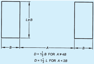
The depth of exploration required depends on the type of proposed structure, its total weight, the size, shape and disposition of the loaded areas, soil profile, and the physical properties of the soil that constitutes each individual stratum. Normally, it should be one and a half times the width of the footing below foundation level. In certain cases, it may be necessary to take at least one bore hole or cone test or both to twice the width of the foundation. If a number of loaded areas are in close proximity the effect of each is additive. In such cases, the whole of the area may be considered as loaded and exploration should be carried out up to one and a half times the lower dimension. In weak soils, the exploration should be continued to a depth at which the loads can be carried by the stratum in question without undesirable settlement and shear failure. In any case, the depth to which seasonal variations affect the soil should be regarded as the minimum depth for the exploration of sites. But where industrial processes affect the soil characteristics this depth may be more. The presence of fast growing and water seeking trees also contributes to the weathering processes.
NOTE — Examples of fast growing and water seeking trees are Banyan (Ficus bengalensis), Pipal (Ficus religiosa) and Neem (Azadirachta indica).
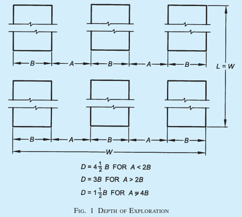
3.2.3.1 An estimate of the variation with depth of the vertical normal stress in the soil arising from foundation loads may be made on the basis of elastic theory. The net loading intensity at any level below a foundation may be obtained approximately by assuming a spread of load of two vertical to one horizontal from all sides of the foundations, due allowance being made for the overlapping effects of load from closely spaced footings. As a general guidance, the depth of exploration at the start of the work may be decided as given in Table 1, which may be modified as exploration proceeds, if required. However, for plant and other main structures, the depth of exploration may be decided depending upon importance of structure, loading conditions and type as well as uniformity of strata.
3.3 Choice of Method for Site Exploration
The choice of the method depends on the following factors.
3.3.1 Nature of Ground
a) Soils — In clayey soils, borings are suitable for deep exploration and pits for shallow exploration. In case of soft sensitive clayey soils field vane shear test may be carried out with advantage.
In sandy soils, special equipments may be required for taking representative samples below the water table. Standard penetration test, dynamic cone penetration test and static cone penetration test are used to assess engineering properties.
b) Gravel-boulder deposits — In the deposits where gravel-boulder proportion is large (>30 percent), the sub-soil strata should be explored by open trial pits of about 5 m × 5 m but in no case less than 2 m × 2 m. The depth of excavation may be up to 6 m. For determining strata characteristics, in-situ tests should be preferred. For shear characteristics and allowable soil pressure dynamic cone penetration tests, load tests on cast in-situ footing and in-situ shear tests that is, boulder-boulder test or concrete-boulder test are more appropriate. For detailed information on these tests reference may be made to good practice [6-2(2)]. Depending on the structure, if required, the strata may be explored by drilling bore hole using suitable method.
c) Rocks — Drillings are suitable in hard rocks and pits in soft rocks. Core borings are suitable for the identification of types of rock, but they cannot supply data on joints and fissures which can be examined only in pits and large diameter borings.
3.3.2 Topography
In hilly country, the choice between vertical openings (for example, borings and trial pits) and horizontal openings (for example, headings) may depend on the geological structure, since steeply inclined strata are most effectively explored by headings and horizontal strata by trial pits or borings. Swamps and areas overlain by water are best explored by borings which may require use of a floating craft.
3.3.3 Cost
For deep exploration, borings are usual, as deep shafts are costly. For shallow exploration in soil, the choice between pits and borings will depend on the nature of the ground and the information required for shallow exploration in rock; the cost of bringing a core drill to the site will be justified only if several holes are required; otherwise, trial pits will be more economical.
Table 1Depth of Exploration (Clause 3.2.3.1)
Sl No.
Type of Foundation
Depth of ExplorationD
(1)
(2)
(3)
i)
Isolated spread footing or raft
3.4 Sampling
3.4.1 Methods of Sampling
a) Disturbed samples — These are taken by methods which modify or destroy the natural structure of the material though with suitable precautions the natural moisture content can be preserved.
b) Undisturbed samples — These are taken by methods which preserve the structure and properties of the material. Such samples are easily obtained from most rocks, but undisturbed samples of soil can be obtained only by special methods. Thin walled tube samples may be used for undisturbed samples in soils of medium strength and tests for the same may be carried out in accordance with good practice [6-2(1)].
NOTE — In case of loose sandy soils and soft soils, specially below water table it may not be possible to take undisturbed sample, in which case other suitable methods may be adopted for exploration.
c) Representative samples — These samples have all their constituent parts preserved, but may or may not be structurally disturbed.
[Clause 3.4.2(a)]
3.4.1.1 The methods usually employed are:
Nature of Ground(1)
Type of Sample(2)
Method of Sampling(3)
Soil
Disturbed
Chunk samplesAuger samples (for example, in clay)Shell samples (for example, in sand)
Undisturbed
Chunk samplesTube samples
Rock
Disturbed
Wash samples from percussion of rotary drilling
Undisturbed
Core barrel sampling
3.4.2 Soil Samples
a) Disturbed soil samples — The mass of sample generally required for testing purposes is given in Table 2.
b) Undisturbed soil samples — The minimum diameter of the sample shall be 38 mm with the minimum length/diameter ratio of 2.
3.4.3 Rock Sample
a) Disturbed samples — The sludge from percussion borings, or from rotary borings which have failed to yield a core, may be taken as a disturbed sample.
b) Undisturbed samples
Block samples — Such samples taken from the rock formation shall be dressed to a size convenient for packing to about 90 mm × 75 mm × 50 mm.
Core sample; see also good practice [6-2(3)]
3.4.4 Protection, Handling and Labelling of Samples
Care should be taken in protecting, handling and subsequent transport of samples and in their full labelling, so that samples can be received in a fit state for examination and testing, and can be correctly recognized as coming from a specified trial pit or boring.
5Materials
5.1 Cement, coarse aggregate, fine aggregate, lime, SURKHI, steel, timber and other materials go into the construction of foundations shall conform to the requirements of Part 5 ‘Building Materials’.
5.2 Protection Against Deterioration of Materials
Where a foundation is to be in contact with soil, water or air, that is, in a condition conducive to the deterioration of the materials of the foundation, protective measures shall be taken to minimize the deterioration of the materials.
5.2.1 Concrete
In the case of concrete placed against a soil containing harmful chemicals (sulphates, chlorides), among other protective measures, it shall be ensured to provide nominal cover required as prescribed in Part 6 ‘Structural Design, Section 5 Concrete for the Applicable Environment Exposure Condition’.
5.2.1.1 Preferably concrete of higher grade shall be used in situations subject to aggressive environment.
5.2.2 Timber
Where timber is exposed to soil, it shall be treated in accordance with good practice [6-2(6)].
7Shallow Foundations
7.0 Design Information
For the satisfactory design of foundations, the following information is necessary:
a) The type and condition of the soil or rock to which the foundation transfers the loads;
b) The general layout of the columns and loadbearing walls showing the estimated loads, including moments and torques due to various loads (dead load, imposed load, wind load, seismic load) coming on the foundation units;
c) The allowable bearing pressure of the soils;
d) The changes in ground water level, drainage and flooding conditions and also the chemical conditions of the subsoil water, particularly with respect to its sulphate content;
e) The behaviour of the buildings, topography and environment/surroundings adjacent to the site, the type and depths of foundations and the bearing pressure assumed; and
f) Seismic zone of the region.
5.2Terminology for Earthquake Engineering of Buildings
5.2.1 For the purpose of earthquake resistant design
of buildings in this standard, the following definitions shall apply:
5.2.2 Base
It is the level at which inertia forces generated in the structure are transferred to the foundation, which then transfers these forces to the ground.
5.2.3 Base Dimensions (d)
Base dimension of the building along a direction is the dimension at its base, in metres, along that direction.
5.2.4 Centre of Mass
The point through which the resultant of the masses of a system acts. This point corresponds to the centre of gravity of masses of system.
5.2.5 Centre of Stiffness
The point through which the resultant of the restoring forces of a system acts.
5.2.6 Design Eccentricity (edi)
It is the value of eccentricity to be used at floor i in torsion calculations for design.
5.2.7 Design Seismic Base Shear (VB)
It is the total design lateral force at the base of a structure.
5.2.8 Diaphragm
It is a horizontal, or nearly horizontal system, which transmits lateral forces to the vertical resisting elements, for example, reinforced concrete floors and horizontal bracing systems.
5.2.9 Dual System
Buildings with dual system consist of shear walls (or braced frames) and moment resisting frames such that:
a) the two systems are designed to resist the total design lateral force in proportion to their lateral stiffness considering the interaction of the dual system at all floor levels; and
b) the moment resisting frames are designed to independently resist at least 25 percent of the design base shear.
5.2.10 Height of Floor (hi)
It is the difference in levels between the base of the building and that of floor i.
5.2.11 Height of Structure (h)
It is the difference in levels, in metres, between its base and its highest level.
5.2.12 Horizontal Bracing System
It is a horizontal truss system that serves the same function as a diaphragm.
5.2.13 Joint
It is the portion of the column that is common to other members, for example, beams, framing into it.
5.2.14 Lateral Force Resisting Element
It is part of the structural system assigned to resist lateral forces.
5.2.15 Moment-Resisting Frame
It is a frame in which members and joints are capable of resisting forces primarily by flexure.
5.2.15.1 Ordinary moment-resisting frame
It is a moment-resisting frame not meeting special detailing requirements for ductile behaviour.
5.2.15.2 Special moment-resisting frame
It is a moment-resisting frame specially detailed to provide ductile behaviour and comply with the requirements given in IS 4326 or IS 13920 or SP 6(6).
5.2.16 Number of Storeys (n)
Number of storeys of a building is the number of levels above the base. This excludes the basement storeys, where basement walls are connected with the ground floor deck or fitted between the building columns. But, it includes the basement storeys, when they are not so connected.
5.2.17 Principal Axes
Principal axes of a building are generally two mutually perpendicular horizontal directions in plan of a building along which the geometry of the building is oriented.
5.2.18 P − Δ Effect
It is the secondary effect on shears and moments of frame members due to action of the vertical loads, interacting with the lateral displacement of building resulting from seismic forces.
5.2.19 Shear Wall
It is a wall designed to resist lateral forces acting in its own plane.
5.2.20 Soft Storey
It is one in which the lateral stiffness is less than 70 percent of that in the storey above or less than 80 percent of the average lateral stiffness of the three storeys above.
5.2.21 Static Eccentricity (esi)
It is the distance between centre of mass and centre of rigidity of floor i.
5.2.22 Storey
It is the space between two adjacent floors.
5.2.23 Storey Drift
It is the displacement of one level relative to the other level above or below.
5.2.24 Storey Shear (V )
It is the sum of design lateral forces at all levels above the storey under consideration.
5.2.25 Weak Storey
It is one in which the storey lateral strength is less than 80 percent of that in the storey above. The storey lateral strength is the total strength of all seismic force resisting elements sharing the storey shear in the considered direction.
7.2Pad or Spread and Strip Foundations
7.2.1 In such type of foundations wherever the resultant of the load deviates from the centre line by more than 1/6 of its least dimension at the base of footing, it should be suitably reinforced.
7.2.2 For continuous wall foundations (plain or reinforced) adequate reinforcement should be provided particularly at places where there is abrupt change in magnitude of load or variation in ground support.
7.2.3 On sloping sites the foundation should have a horizontal bearing and stepped and lapped at changes of levels for a distance at least equal to the thickness of foundation or twice the height of step whichever is greater. The steps should not be of greater height than thickness of the foundations.
7.2.4 Ground Beams
The foundation can also have the ground beam for transmitting the load. The ground beam carrying a load bearing wall should be designed to act with the wall forming a composite beam, when both are of reinforced concrete and structurally connected by reinforcement.
The ground beam of reinforced concrete structurally connected to reinforced brick work can also be used.
7.2.5 Dimensions of Foundation
The dimensions of the foundation in plan should be such as to support loads as given in good practice [6-2(11)]. The width of the footings shall be such that maximum stress in the concrete or masonry is within the permissible limits. The width of wall foundation (in mm) shall not be less than that given by:
B = W + 3 0 0
where
B = Width at base in mm, and
W = Width of supported wall in mm.
7.2.6 In the base of foundations for masonry foundation it is preferable to have the steps in multiples of thickness of masonry unit.
7.2.7 The plan dimensions of excavation for foundations should be wide enough to ensure safe and efficient working with good practice [6-2(12)].
7.2.8 Unreinforced foundation may be of concrete or masonry (stone or brick) provided that angular spread of load from the base of column/wall or bed plate to the outer edge of the ground bearing is not more than 1 vertical to ½ horizontal to masonry or 1 vertical to 1 horizontal for cement concrete and 1 vertical to 2/3 horizontal for lime concrete. The minimum thickness of the foundation of the edge should not be less than 150 mm. In case the depth to transfer the load to the ground bearing is less than the permissible angle of spread, the foundations should be reinforced.
7.2.9 If the bottom of a pier is to be belled so as to increase its load carrying capacity such bell should be at least 300 mm thick at its edge. The sides should be sloped at an angle of not less than 45° with the horizontal. The least dimension should be 600 mm (circular, square or rectangular). The design should allow for the vertical tilt of the pier by 1 percent of its height.
7.2.10 If the allowable bearing capacity is available only at a greater depth, the foundation can be rested at a higher level for economic considerations and the difference in level between the base of foundation and the depth at which the allowable bearing capacity occurs can be filled up with either: (a) concrete of allowable compressive strength not less than the allowable bearing pressure, (b) in compressible fill material, for example, sand, gravel, etc, in which case the width of the fill should be more than the width of the foundation by an extent of dispersion of load from the base of the foundation on either side at the rate of 2 vertical to 1 horizontal.
7.2.11 The cement concrete foundation (plain or reinforced) should be designed in accordance with good practice [6-2(13)] and masonry foundation in accordance with good practice [6-2(14)].
7.2.12 Thickness of Footing
The thickness of different types of footings, if not designed according to 7.1, should be as given in Table 5.
7.2.13 Land Slip Area
On a sloping site, spread foundation shall be on a horizontal bearing and stepped. At all changes of levels, they shall be lapped at the steps for a distance at least equal to the thickness of the foundation or twice the height of the step, whichever is greater. The steps shall not be of greater height than the thickness of the foundation unless special precautions are taken. On sloping ground on clay soils, there is always a tendency for the upper layers of soil to move downhill, depending on type of soil, the angle of slope, climatic conditions, etc. Special precautions are necessary to avoid such a failure.
7.2.14 In the foundations, the cover to the reinforcement shall be as prescribed in Part 6 ‘Structural Design, Section 5 Concrete for the Applicable Environment Exposure Condition’.
7.2.15 For detailed information regarding preparation of ground work, reference may be made to good practice [6-2(15)].
7.3Raft Foundations
7.3.1 Design Considerations
Design provisions given in 7.1 shall generally apply.
7.3.1.1 The structural design of reinforced concrete rafts shall conform to Part 6 ‘Structural Design, Section 5 Concrete’.
7.3.1.2 In the case of raft, whether resting on soil directly or on lean concrete, the cover to the reinforcement shall be as prescribed in Part 6 ‘Structural Design, Section 5 Concrete’ for the applicable environment exposure condition.
7.3.1.3 In case the structure supported by the raft consists of several parts with varying loads and heights, it is advisable to provide separation joints between these parts. Joints shall also be provided wherever there is a change in the direction of the raft.
7.3.1.4 Foundations subject to heavy vibratory loads should preferably be isolated.
7.3.1.5 The minimum depth of foundation shall generally be not less than 1 m.
7.3.1.5 Dimensional parameters
The size and shape of the foundation adopted affect the magnitude of subgrade modulus and long-term deformation of the supporting soil and this, in turn, influences the distribution of contact pressure. This aspect needs to be taken into consideration in the analysis.
7.3.1.7 Eccentricity of loading
A raft generally occupies the entire area of the building and often it is not feasible and rather uneconomical to proportion it coinciding the centroid of the raft with the line of action of the resultant force. In such cases, the effect of the eccentricity on contact pressure distribution shall be taken into consideration.
7.3.1.8 Properties of supporting soil
Distribution of contact pressure underneath a raft is affected by the physical characteristics of the soil supporting it. Consideration must be given to the increased contact pressure developed along the edges of foundation on cohesive soils and the opposite effect
Table 5 Thickness of Footings(Clause 7.2.12)
Sl No.(1)
Type of Footings(2)
Thickness of Footings, Min(3)
Remarks(4)
i)
Masonry
a)
250 mmb) Twice the maximum projection from the face of the wall
Select the greater of the two values
ii)
Plain concrete
For normal structures
a)
200 mmb) Twice the maximum offset in a stepped footingc) 300 mm
—For footings resting on top of the pile
For lightly loaded structures
a)
150 mmb) 200 mm
For footings resting on soilResting on soilResting on pile
iii)
Reinforced concrete
a)
150 mmb) 300 mm
Resting on soilResting on pile
on granular soils. Long-term consolidation of deep soil layers shall be taken into account in the analysis. This may necessitate evaluation of contact pressure distribution both immediately after construction and after completion of the consolidation process. The design must be based on the worst conditions.
7.3.1.9 Rigidity of foundations
Rigidity of the foundation tends to iron out uneven deformation and thereby modifies the contact pressure distribution. High order of rigidity is characterized by long moments and relatively small, uniform settlements. A rigid foundation may also generate high secondary stresses in structural members. The effect of rigidity shall be taken into account in analysis.
7.3.1.10 Rigidity of the superstructure
Free response of the foundations to soil deformation is restricted by the rigidity of the superstructure. In the extreme case, a stiff structure may force a flexible foundation to behave as rigid. This aspect shall be considered to evaluate the validity of the contact pressure distribution.
7.3.1.11 Modulus of elasticity and modulus of subgrade reaction
Annex A enumerates the methods of determination of modulus of elasticity (E ). The modulus of subgrade reaction (k) may be determined in accordance with Annex B.
7.3.2 Necessary Information
The following information is necessary for a satisfactory design and construction of a raft foundation:
a) Site plan showing the location of the proposed as well as the neighbouring structures;
b) Plan and cross-sections of building showing different floor levels, shafts and openings, etc, layout of loading bearing walls, columns, shear walls, etc;
c) Loading conditions, preferably shown on a schematic plan indicating combination of design loads transmitted to the foundation;
d) Information relating to geological history of the area, seismicity of their area, hydrological information indicating ground water conditions and its seasonal variations, etc;
e) Geotechnical information giving subsurface profile with stratification details, engineering properties of the founding strata (namely, index properties, effective shear parameters determined under appropriate drainage conditions, compressibility characteristics, swelling properties, results of field tests like
static and dynamic penetration tests, pressure meter tests etc); and
f) A review of the performance of similar structure, if any, in the locality.
7.3.3 Choice of Raft Type
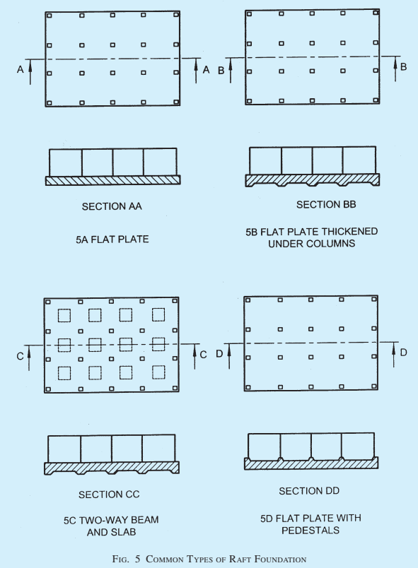
7.3.3.1 For fairly small and uniform column spacing and when the supporting soil is not too compressible a flat concrete slab having uniform thickness throughout (a true mat) is most suitable (see Fig. 5A).
7.3.3.2 A slab may be thickened under heavy loaded columns to provide adequate strength for shear and negative moment. Pedestals may also be provided in such cases (see Fig. 5B).
7.3.3.3 A slab and beam type of raft is likely to be more economical for large column spacing and unequal column loads particularly when the supporting soil is very compressive (see Fig. 5C and 5D).
7.3.3.4 For very heavy structures, provision of cellular raft or rigid frames consisting of slabs and basement walls may be considered.
7.3.4 Methods of Analysis
The essential task in the analysis of a raft foundation is the determination of the distribution of contact pressure underneath the raft which is a complex function of the rigidity of the superstructure, the supporting soil and the raft itself, and cannot be determined with exactitude, except in very simple cases. This necessitates a number of simplifying assumptions to make the problem amenable to analysis. Once the distribution of contact pressure is determined, design bending moments and shears can be computed based on statics. The methods of analysis suggested are distinguished by the assumptions involved. Choice of a particular method should be governed by the validity of the assumptions in the particular case.
7.3.4.1 Rigid foundation (conventional method)
This method is based on the assumption of linear distribution of contact pressure. The basic assumptions of this method are:
a) the foundations rigid relative to the supporting soil and the compressible soil layer is relatively shallow; and
b) the contact pressure variation is assumed as planar, such that the centroid of the contact pressure coincides with the line of action of the resultant force of all loads acting on the foundation.
This method may be used when either of the following conditions is satisfied:
a) The structure behaves as rigid (due to the
combined action of the superstructure and the foundation) with relative stiffness factor K > 0.5 (for evaluation of Ksee Annex C); and
b) The column spacing is less than 1.75/γ (see Annex C).
The raft is analysed as a whole in each of the two perpendicular directions. The contact pressure distribution is determined by the procedure outlined in Annex D. Further analysis is also based on statics.
In the case of uniform conditions when the variations in adjacent column loads and column spacings do not exceed 20 percent of the higher value, the raft may be divided into perpendicular strips of widths equal to the distance between midspans and each strip may be analysed as an independent beam with known column loads and known contact pressures. Such beams will not normally satisfy statics due to shear transfer between adjacent strips and design may be based on suitable moment coefficients, or by moment distribution.
NOTE — On soft soils, for example, normally consolidated clays, peat, muck, organic silts, etc, the assumptions involved in the conventional method are commonly justified.
7.3.4.2 Flexible foundations
a) Simplified method — In this method, it is assumed that the subgrade consists of an infinite array of individual elastic springs each of which is not affected by others. The spring constant is equal to the modulus of subgrade reaction (k). The contact pressure at any point under the raft is, therefore, linearly proportional to the settlement at the point. Contact pressure may be determined as given in Annex E. This method may be used when all the following conditions are satisfied:
7.4 Ring Foundations
For provisions regarding ring foundations good practice [6-2(16)] shall be referred to.
7.1Design Considerations
7.1.1 Design Loads
The foundation shall be proportioned for the following combination of loads:
a) Dead load + imposed load; and
b) Dead load + imposed load + wind load or seismic loads, whichever is critical.
For details, reference shall be made to Part 6 ‘Structural Design, Section 1 Loads, Forces and Effects’.
NOTES
1 For load, imposed, wind, seismic and other loads, see Part 6 ‘Structural Design, Section 1 Loads, Forces and Effects’.
2 For coarse grained soils, settlements shall be estimated corresponding to 7.1.1 (b) and for fine grained soils settlement shall be estimated corresponding to permanent loads only.
7.1.2 Allowable Bearing Pressure
The allowable bearing pressure shall be taken as either of the following, whichever is less:
a) The safe bearing capacity on the basis of shear strength characteristics of soil, or
b) The allowable bearing pressure that the soil can take without exceeding the permissible settlement (see 7.1.3).
7.1.2.1 Bearing capacity by calculation
Where the engineering properties of the soil are available, that is, cohesion, angle of internal friction, density, etc the bearing capacity shall be calculated
from stability considerations of shear; factor of safety of 2.5 shall be adopted for safe bearing capacity. The effect of interference of different foundations should be taken into account. The procedure for determining the ultimate bearing capacity and allowable bearing pressure of shallow foundations based on shear and allowable settlement criteria shall be in accordance with good practice [6-2(7)].
7.1.2.2 Field method for determining allowable bearing pressure
Where appropriate, plate load tests can be performed and allowable pressure determined as per good practice [6-2(8)]. The allowable bearing pressure for sandy soils may also be obtained by loading tests. When such tests cannot be done, the allowable bearing pressure for sands may be determined using penetration test.
7.1.2.3 Where the bearing materials directly under a foundation over-lie a stratum having smaller safe bearing capacity, these smaller values shall not be exceeded at the level of such stratum.
7.1.2.4 Effect of wind and seismic force
Where the bearing pressure due to wind is less than 25 percent of that due to dead and live loads, it may be neglected in design. Where this exceeds 25 percent foundations may be so proportioned that the pressure due to combined dead, live and wind loads does not exceed the allowable bearing pressure by more than 25 percent.
When earthquake forces are considered for the computation of design loads, the permissible increase in allowable bearing pressure of pertaining soil shall be as given in Table 3, depending upon the type of foundation of the structure.
7.1.2.5 Bearing capacity of buried strata
If the base of a foundation is close enough to a strata of lower bearing capacity, the latter may fail due to excess pressure transmitted to it from above. Care should be taken to see that the pressure transmitted to the lower strata is within the prescribed safe limits. When the footings are closely spaced, the pressure transmitted to the underlying soil will overlap. In such cases, the pressure in the overlapped zones will have to be considered. With normal foundations, it is sufficiently accurate to estimate the bearing pressure on the underlying layers by assuming the load to be spread at a slope of 2 (vertical) to 1 (horizontal).
7.1.3 Settlement
The permissible values of total and differential settlement for a given type of structure may be taken as given in Table 4. Total settlements of foundation due to net imposed loads shall be estimated in accordance with good practice [6-2(10)]. The following
causes responsible for producing the settlement shall be investigated and taken into account.
a) Causes of settlement
Elastic compression of the foundation and the underlying soil;
Consolidation including secondary compression;
Ground water lowering — Specially repeated lowering and raising of water level in loose granular soils tend to compact the soil and cause settlement of the footings. Prolonged lowering of the water table in fine grained soils may introduce settlement because of the extrusion of water from the voids. Pumping water or draining water by tiles or pipes from granular soils without an adequate mat of filter material as protection may, in a period of time, carry a sufficient amount of fine particles away from the soil and cause settlement;
Seasonal swelling and shrinkage of expansive clays;
Ground movement on earth slope, for example, surface erosion, slow creep or landslides; and
Other causes, such as adjacent excavation, mining, subsidence and underground erosion.
Causes of differential settlements
Geological and physical non-uniformity or anomalies in type, structure, thickness, and density of the soil medium (pockets of sand in clay, clay lenses in sand, wedge like soil strata, that is, lenses in soil), an admixture of organic matter, peat, mud;
Non-uniform pressure distribution from foundation to the soil due to non-uniform loading and incomplete loading of the foundations;
Water regime at the construction site,
Overstressing of soil at adjacent site by heavy structures built next to light ones;
Overlap of stress distribution in soil from adjoining structures;
Unequal expansion of the soil due to excavation for footing;
Non-uniform development of extrusion settlements; and
Non-uniform structural disruptions or disturbance of soil due to freezing and thawing, swelling and softening and drying of soils.
Table 3 Percentage of Permissible Increase in Allowable Bearing Pressure or Resistance of Soils
(Clauses 7.1.2.4 and 8.2.7)
Sl No.
Foundation
Type of Soil Mainly Constituting the Foundation
7.1.4 Depth of Foundations
7.1.4.1 The depth to which foundations should be carried depends upon the following principal factors:
a) The securing of adequate allowable capacity.
b) In the case of clayey soils, penetration below the zone where shrinkage and swelling due to seasonal weather changes, and due to trees and shrubs are likely to cause appreciable movements.
c) In fine sands and silts, penetration below the zone in which trouble may be expected from frost.
d) The maximum depth of scour, wherever relevant, should also be considered and the foundation should be located sufficiently below this depth.
e) Other factors such as ground movements and heat transmitted from the building to the supporting ground may be important.
7.1.4.2 All foundations shall extend to a depth of at least 500 mm below natural ground level. On rock or such other weather resisting natural ground, removal of the top soil may be all that is required. In such cases, the surface shall be cleaned and, if necessary, stepped or otherwise prepared so as to provide a suitable bearing and thus prevent slipping or other unwanted movements.
7.1.4.3 Where there is excavation, ditch pond, water course, filled up ground or similar condition adjoining or adjacent to the subsoil on which the structure is to be erected and which is likely to impair the stability of structure, either the foundation of such structure shall be carried down to a depth beyond the detrimental influence of such conditions, or retaining walls or similar works shall be constructed for the purpose of shielding from their effects.
7.1.4.4 A foundation in any type of soil shall be below the zone significantly weakened by root holes or cavities produced by burrowing animals or works. The depth shall also be enough to prevent the rainwater scouring below the footings.
7.1.4.5 Clay soils, like black cotton soils, are seasonally affected by drying, shrinkage and cracking in dry and hot weather, and by swelling in the following wet weather to a depth which will vary according to the nature of the clay and the climatic condition of the region. It is necessary in these soils, either to place the foundation bearing at such a depth where the effects of seasonal changes are not important or to make the foundation capable of eliminating the undesirable effects due to relative movement by providing flexible type of construction or rigid foundations. Adequate
load counteracting against swelling pressures also provide satisfactory foundations.
7.1.5 Foundation at Different Levels
7.1.5.1 Where footings are adjacent to sloping ground or where the bottoms of the footings of a structure are at different levels or at levels different from those of the footings of adjoining structures, the depth of the footings shall be such that the difference in footing elevations shall be subject to the following limitations:
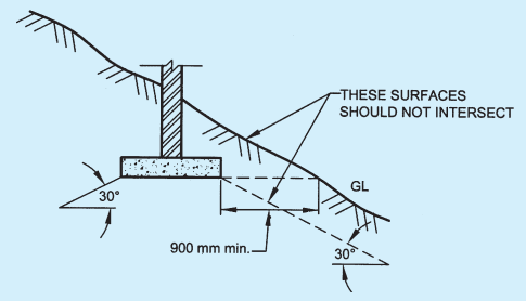
a) When the ground surface slopes downward adjacent to a footing, the sloping surface shall not intersect a frustum of bearing material under the footing having sides which make an angle of 30° with the horizontal for soil and horizontal distance from the lower edge of the footing to the sloping surface shall be at least 600 mm for rock and 900 mm for soil (see Fig. 2).
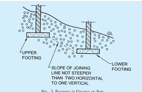
b) In the case of footings in granular soil, a line drawn between the lower adjacent edges of adjacent footings shall not have a steeper slope than one vertical to two horizontal (see Fig. 3).
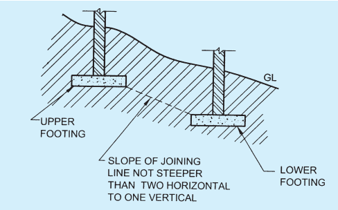
In case of footing of clayey soils a line drawn between the lower adjacent edge of the upper footing and the upper adjacent edge of lower footing shall not have a steeper slope than one vertical to two horizontal (see Fig. 4).
7.1.5.2 The requirement given in 7.1.5.1 shall not apply under the following conditions:
a) Where adequate provision is made for the lateral support (such as, with retaining walls) of the material supporting the higher footing.
b) When the factor of safety of the foundation soil against shearing is not less than four.
7.1.6 Effect of Seasonal Weather Changes
During periods of hot, dry weather a deficiency of water develops near the ground surface and in clay soils, that is associated with a decrease of volume or ground shrinkage and the development of cracks. The shrinkage of clay will be increased by drying effect produced by fast growing and water seeking trees. The range of influence depends on size and number of trees and it increase during dry periods. In general, it is desirable that there shall be a distance of at least 8 m between such trees. Boiler installations, furnaces, kilns, underground cables and refrigeration installations and other artificial sources of heat may also cause increased volume changes of clay by drying out the ground beneath them, the drying out can be to a substantial depth. Special precautions either in the form of
FIG. 2 FOOTING IN SLOPING GROUND
FIG. 3 FOOTING IN GRANULAR SOIL
FIG. 4 FOOTING IN CLAYEY SOIL
insulation or otherwise should be taken. In periods of wet weather, clay soils swell and the cracks lend to close, the water deficiency developed in the previous dry periods may be partially replenished and a subsurface zone or zones deficient in water may persist for many years. Leakage from water mains and underground sewers may also result in large volume changes. Therefore, special care must be taken to prevent such leakages.
7.1.7 Effect of Mass Movements of Ground in Unstable Areas
7.1.7.1 In certain areas mass movements of the ground are liable to occur from causes independent of the loads applied by the foundations of structures. These include mining subsidence, landslides on unstable slopes and creep on clay slopes.
7.1.7.2 Mining subsidence
In mining areas, subsidence of the ground beneath a building or any other structure is liable to occur. The magnitude of the movement and its distribution over the area are likely to be uncertain and attention shall, therefore, be directed to make the foundations and structures sufficiently rigid and strong to withstand the probable worst loading condition.
7.1.7.3 Landslide prone areas
The construction of structures on slopes which are suspected of being unstable and are subject to landslip shall be avoided.
On sloping ground on clay soils, there is always a tendency for the upper layers of soil to move downhill, depending on type of soil, the angle of slope, climatic conditions, etc. In some cases, the uneven surface of the slope on a virgin ground will indicate that the area is subject to small land slips and, therefore, if used for foundation, will obviously necessitate special design consideration.
Where there may be creep of the surface layer of the soil, protection against creep may be obtained by following special design considerations.
On sloping sites, spread foundations shall be on a horizontal bearing and stepped. At all changes of levels, they shall be lapped at the steps for a distance at least equal to the thickness of the foundation or twice the height of the step, whichever is greater. The steps shall not be of greater height than the thickness of the foundation, unless special precautions are taken.
Cuttings, excavations or sloping ground near and below foundation level may increase the possibility of shear failure of the soil. The foundation shall be well beyond the zone of such shear failure.
If the probable failure surface intersects a retaining wall or other revetment, the latter shall be made strong enough to resist any unbalanced thrust. In case of doubt as to the suitability of the natural slopes or cuttings, the structure shall be kept well away from the top of the slopes, or the slopes shall be stabilized.
Cuttings and excavations adjoining foundations reduce stability and increase the likelihood of differential settlement. Their effect should be investigated not only when they exist but also when there is possibility that they are made subsequently.
Where a structure is to be placed on sloping ground, additional complications are introduced. The ground itself, particularly if of clay, may be subject to creep or other forms of instability, which may be enhanced if the strata dip in the same direction as the ground surface. If the slope of the ground is large, the overall stability of the slope and substructure may be affected. These aspects should be carefully investigated.
7.1.8 Precautions for Foundations on Inclined Strata
In the case of inclined strata, if they dip towards a cutting of basement, it may be necessary to carry foundation below the possible slip planes, land drainage also requires special consideration, particularly on the uphill side of a structure to divert the natural flow of water away from the foundations.
7.1.9 Strata of Varying Thickness
Strata of varying thickness, even at appreciable depth, may increase differential settlement. Where necessary, calculations should be made of the estimated settlement from different thickness of strata and the structure should be designed accordingly. When there is large change of thickness of soft strata, the stability of foundation may be affected. Site investigations should, therefore, ensure detection of significant variations in strata thickness.
7.1.10 Layers of Softer Material
Some soils and rocks have thin layers of softer material between layers of harder material, which may not be detected unless thorough investigation is carried out. The softer layers may undergo marked changes in properties if the loading on them is increased or decreased by the proposed construction or affected by related changes in ground water conditions. These should be taken into account.
7.1.11 Spacing Between Existing and New Foundation
The deeper the new foundation and the nearer to the existing it is located, the greater the damage is likely to be. The minimum horizontal spacing between existing and new footings shall be equal to the width of the wider one. While the adoption of such provision
shall help minimizing damage to adjacent foundation, an analysis of bearing capacity and settlement shall be carried out to have an appreciation of the effect on the adjacent existing foundation.
7.1.12 Alterations During Construction
a) Where during construction the soil or rock to which foundation is to transfer loads is found not to be the type or in the condition assumed, the foundation shall be re-designed and constructed for the existing type or conditions and the Authority notified.
b) Where a foundation bears on gravel, sand or silt and where the highest level of the ground water is or likely to be higher than an elevation defined by bearing surface minus the width of the footing, the bearing pressure shall be altered in accordance with Note 4 in Table 3.
c) Where the foundation has not been placed or located as indicated earlier or is damaged or bears on a soil whose properties may be adversely changed by climatic and construction conditions, the error shall be corrected, the damaged portion repaired or the design capacity of the affected foundation recalculated to the satisfaction of the Authority.
d) Where a foundation is placed, and if the results of a load test so indicate, the design of the foundation shall be modified to ensure structural stability of the same.
8.1Material
8.1.1 Concrete
The minimum grade of concrete to be used shall not be less than that arrived at in accordance with Part 6 ‘Structural Design, Section 5 Concrete’.
8.1.1.1 For bored and driven cast-in-situ concrete piles including under-reamed piles
The minimum cement content shall be 400 kg/m3 in all conditions. For piles up to 6 m, minimum cement content of 350 kg/m3 without provision for under water concreting may be used under favourable non-aggressive subsoil condition and where concrete of higher strength is not needed structurally or due to aggressive site conditions. For concreting in aggressive surroundings due to presence of sulphates, etc the provisions given in Part 6 ‘Structural Design, Section 5 Concrete’ shall be followed.
8.1.2 Steel Reinforcement
Steel reinforcement shall conform to any one of the types of steel specified in Part 6 ‘Structural Design, Section 5 Concrete’.
8Driven/bored Cast In-situ Concrete Piles
8.0 General
Piles find application in foundations to transfer load from a structure to competent sub-surface strata having adequate load bearing capacity. The load transfer mechanism from a pile to the surrounding ground is complicated and is yet to be fully understood, although
application of pile foundations is in practice over many decades. Broadly, piles transfer axial loads either substantially by friction along their shafts and/or substantially by the end bearing. Construction of a pile foundation requires a careful choice of piling system, depending upon the subsoil conditions, the load characteristics of a structure and the limitation of total settlement, differential settlements and any other special requirement of a project.
8.2Design Considerations
Pile foundation shall be designed in such a way that the load from the structure it supports can be transmitted to the soil without causing any soil failure and without causing such settlement, differential or total under permanent/transient loading as may result in structural damage and/or functional distress. The pile shaft should have adequate structural capacity to withstand all loads (vertical, axial or otherwise) and moments which are to be transmitted to the subsoil.
NOTE — When working near existing structures, care shall be taken to avoid any damage to structures.
8.2.1 Soil Resistance
The bearing capacity of a pile is dependent on the properties of the soil in which it is embedded. Axial load from a pile is normally transmitted to the soil through skin friction along the shaft and end bearing at its tip. A horizontal load on a vertical pile is transmitted to the subsoil primarily by horizontal subgrade reaction generated in the upper part of the
shaft. A single pile is normally designed to carry load along its axis. The transverse load bearing capacity of a single pile depends on the soil reaction developed and the structural capacity of the shaft under bending. In case the horizontal loads are of higher magnitude, it is essential to investigate the phenomena using principles of horizontal subsoil reaction adopting appropriate values for horizontal modulus of the soil. Alternatively, piles may be installed in rake. The feasibility of constructing bored piles in rake under a given subsoil condition should, however, be examined critically.
8.2.1.1 The ultimate bearing capacity of a pile may be estimated approximately by means of a static formula on the basis of soil test results or by test loading. The settlement of pile obtained at safe load/ working load from load test results on a single pile shall not be directly used in forecasting the settlement of a structure unless experience from similar foundations on its settlement behaviour is available. The average settlement may be assessed on the basis of subsoil data and loading details of the structure as a whole using the principle of soil mechanics.
8.2.1.2 Static formula
By using static formula, the estimated value of the ultimate bearing capacity of a typical pile is obtained, the accuracy being dependent on the reliability of the formula and the reliability of the soil properties for various strata available. The soil properties to be adopted in such a formula may be assigned from results of laboratory tests and field tests as per good practice [6-2(1)]. Two separate static formulae commonly applicable for cohesive and non-cohesive soils are indicated in Annex G, to serve only as a guide. Other alternative formulae may be applicable, depending on the subsoil characteristics and method of installation of piles.
10Bored Precast Concrete Piles
10.1 Provisions of 9 except 9.3 shall generally apply.
10.2 For grouting the space around the pile, the precast
pile should be provided with a central duct/hole or suitable jet holes to pump the grouting material. The bottom end of the pile shall have proper arrangements for flushing/cleaning for grouting.
10.3 Reinforcement
The longitudinal reinforcement shall be provided in for the entire length preferably of high yield strength to withstand the handling stresses to the extent to meet requirement as given in 9.2.5. All the main longitudinal bars shall be of the same length. The area of the main longitudinal reinforcement of any type and grade shall not be less than 0.4 percent of the cross-section area of the piles or as required to cater for handling stresses whichever is greater. The lateral reinforcement shall be links or spirals preferably of not less than 6 mm diameter bars. The cover of concrete over all the reinforcement including bending wire should not be less than 40 mm, but where the piles are exposed to the sea-water or water having other corrosive contents the cover should be no where less than 50 mm. A thin gauge sheathing pipe of approximately 40 mm diameter may be attached to the reinforcement cage, in case of solid piles, to form the central duct for pumping grout to the bottom of the bore.
10.4 For detailed information regarding casting and curing, storing and handling, control of pile installation and recording of data, reference may be made to good practice [6-2(21)].
11Under-reamed Piles
11.0 General
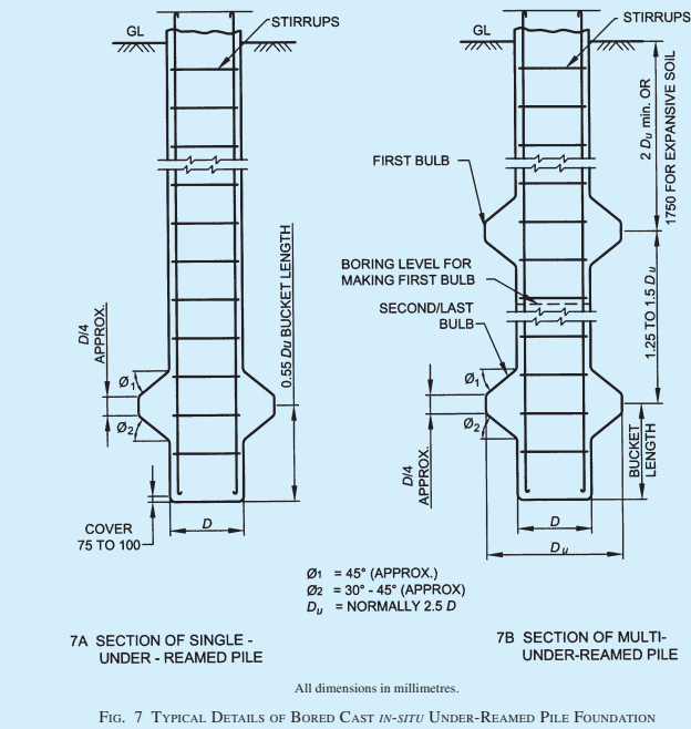
Under-reamed piles are bored cast in-situ and bored compaction concrete types having one or more bulbs formed by enlarging the borehole for the pile stem. These piles are suited for expansive soils which are often subjected to considerable ground movements due to seasonal moisture variations. These also find wide application in other soil strata where economics are favourable. When the ground consists of expansive soil, for example, black cotton soils, the bulb of underreamed pile provide anchorage against uplift due to swelling pressure, apart from the increased bearing, provided topmost bulb is formed close to or just below the bottom of active zone. Negative slopes may not be stable in certain strata conditions, for example, in pure sands (clean sands with fines less than five per cent) and very soft clayey strata having N of SPT less than 2 (undrained shear strength of less than 12.5 kN/m2). Hence formation of bulb(s) in such strata is not advisable. In subsoil strata above water table, the maximum number of bulbs in underreamed pile should be restricted to four. In the strata such as clay, silty clay and clayey silt with high water table where sides
of bore hole stand by itself without needing any stabilization by using drilling mud or otherwise, the maximum number of bulbs in under-reamed piles should be restricted to two. In strata, for example, clayey sand, silty sand and sandy silt with high water table where bore hole needs stabilization by using drilling mud, under-reamed piles with more than one bulb shall not be used. In loose to medium pervious strata such as clayey sand, silty sand and sandy silt strata, compaction under-reamed piles can be used as the process of compaction, increases the load carrying capacity of piles. From practical considerations, under-reamed piles of more than 10 m depth shall not be used without ensuring their construction feasibility and load carrying capacity by initial load tests in advance. In view of additional anchorage available with the provision of bulbs, under-reamed piles can be used with advantage to resist uplift loads.
11.1 Materials
11.1.1 Provisions of 8.1 shall generally apply.
11.2 Design Considerations
11.2.1 General
Under-reamed pile foundation shall be designed in such a way that the load from the structure they support can be transmitted to the soil without causing failure of soil or failure of pile material and without causing settlement (differential or total) under permanent transient loading as may result in structural damage and/or functional distress (see Fig. 7).
9Driven Precast Concrete Piles
9.1 Provisions of 8 except 8.2.9 shall generally apply.
9.2 Design of Piles
9.2.1 The design of pile section shall be such as to ensure the strength and soundness of the pile against lifting from the casting bed, transporting, handling, driving stresses without damage.
9.2.2 Any shape having radial symmetry will be satisfactory for precast piles. The most common cross-sections used are square and octagonal or circular.
9.2.3 Where exceptionally long lengths of piles are required, hollow sections may advantageously be used. If the final conditions require a larger cross-sectional area, the hollow sections may be filled with concrete after driving in position.
9.2.4 Excessive whippiness in handling precast pile may generally be avoided by limiting the length of pile to a maximum of 50 times the least width.
9.2.5 Lifting and Handling Stresses
Stresses induced by bending in the cross-section of a precast pile during lifting and handling may be estimated just as for any reinforced concrete section in accordance with relevant provisions of good practice [6-2(13)]. The calculations with regard to moments depending on the method of support during handling will be as given below. Excessive whippiness in handling precast pile may generally be avoided by limiting the length of pile to a maximum of 50 times the least width.
Number of Points of Pick Up
Location of Point of Support from in Terms of Length of Pile for Minimum Moments
Bending Moment to be Allowed for Design
One
0.293 L
(WL)/(23.3)
Two
0.207 L
(WL)/(46.6)
Three
0.145 L, the middle point will be at the centre
(WL)/(95)
where
W = Mass of pile in kg, and
L = Length in metres.
During hoisting the pile will be suspended at one point near the head and the bending moment will be the least when it is pulled in a distance of 0.293 L, and the value of bending moment will be:
12Timber Piles
12.1 Materials
12.1.1 Timber
The timber shall have the following characteristics:
a) Only structural timber shall be used for piles (see Part 6 ‘Structural Design, Section 3 Timber and Bamboo, 3A Timber’);
b) The length of an individual pile shall be:
the specified length ± 300 mm for piles up to and including 12 m in length, and
the specified length ± 600 mm for piles above 12 m in length;
c) The ratio of heartwood diameter to the pile butt diameter shall be not less than 0.8; and
d) Piles to be used untreated shall have as little sapwood as possible.
12.2 Design Considerations
12.2.1 General — See 8.0.
12.2.2 Soil Resistance — See 8.2.1.
12.2.3 Structural Capacity
The pile shall have the necessary structural strength to transmit the load imposed on it to the soil. Load tests shall be conducted on a single pile or preferably on a group of piles. For compaction piles, test should be done on a group of piles with their caps resting on the ground as good practice [6-2(18)]. If such test data is not available, the load carried by the pile shall be determined by the Engineering News formula (see Note).
NOTE — For timber piles, the load carried shall be determined by the Engineering News formula given below. Care shall be taken that while counting the number of blows, the head of the timber pile is not broomed or brushed and in case of interrupted driving counting shall be done after 300 mm of driving.
For piles driven with drop hammer,
P=
13Other Foundations
13.1 Pier Foundations
13.1.1 Design Considerations
13.1.1.1 General
The design of concrete piers shall conform to the requirements for columns specified in Part 6 ‘Structural Design, Section 5 Concrete’. If the bottom of the pier is to be belled so as to increase its load carrying capacity, such bell shall be at least 300 mm thick at its edge. The sides shall slope at an angle of not less than 60° with the horizontal. The least permissible dimensions shall be 600 mm, irrespective of the pier being circular, square or rectangular. Piers of smaller dimensions if permitted shall be designed as piles (see 8 and 9).
13.1.1.2 Plain concrete piers
The height of the pier shall not exceed 6 times the least lateral dimension. When the height exceeds 6 times
the least lateral dimension, buckling effect shall be taken into account, but in no case shall the height exceed 12 times the least lateral dimension.
When the height exceeds 6 times the least lateral dimension, the deduction in allowable stress shall be given by the following formula:
fc
14Ground Improvement
In poor and weak subsoils, the design of conventional shallow foundation for structures and equipment may present problems with respect to both sizing of foundation as well as control of foundation settlements. A viable alternative in certain situations, developed over the recent years is to improve the subsoil to an extent such that the subsoil would develop an adequate bearing capacity and foundations constructed after subsoil improvement would have resultant settlements within acceptance limits. Selection of ground improvement techniques may be done in accordance with good practice [6-2(25)].
Use of suitable geo-synthetics/geo-textiles may be made in an approved manner for ground improvement, where applicable; see also good practice [6-2(26)].
Determination of Modulus of Elasticity ( E Mathrm S ) and Poisson’s Ratio( ) Μ
A-1 Determination of Modulus of Elasticity (ES)
A-1.1 The modulus of elasticity is a function of composition of the soil, its void *ratio, stress history and loading rate. In granular soils it is a function of the depth of the strata, while in cohesive soil it is markedly influenced by the moisture content. Due to its great sensitivity to sampling disturbance, accurate evaluation of the modulus in the laboratory is extremely difficult. For general cases, therefore, determination of the modulus may be based on field tests (A-2). Where properly equipped laboratory and sampling facility is available, E may be determined in the laboratory (see A-3).
Annex C(Clauses 7.3.4.1, 7.3.4.2 and B-4)
Rigidity of Superstructure and Foundation
C-1 DETERMINATION OF THE RIGIDITY OF THE STRUCTURE
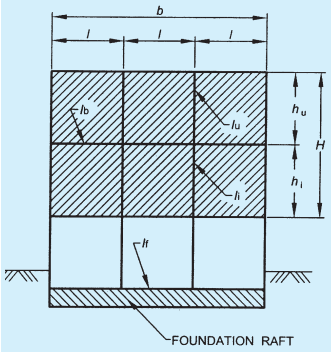
C-1.1 The flexural rigidity EI of the structure of any section may be estimated according to the relation given below (see also Fig. 8)
EI
Annex D(Clause 7.3.4.1)
Calculation of Pressure Distribution by Conventional Method
D-1 Determination of Pressure Distribution
D-1.1 The pressure distribution (q) under the raft shall be determined by the following formula:
q=AQ
2.3.12 Multi-Under-Reamed Pile — An under-reamed pile having more than one bulb. The piles having two bulbs may be called double under-reamed piles.
2.3.13 Negative Skin Friction — Negative skin friction is the force developed through the friction between the pile and the soil in such a direction as to increase the loading on the pile, generally due to drag of a consolidating soft layer around the pile resting on a stiffer bearing stratum such that the surrounding soil settles more than the pile.
2.3.14 Ultimate Load Capacity — The maximum load which a pile can carry before failure of ground when the soils fails by shear or failure of pile materials.
2.3.15 Under-Reamed Pile — A bored cast in-situ or bored compaction concrete pile with enlarged bulb(s) made by either cutting or scooping out the soil or by any other suitable process.
One and a half times the width (B) (see Fig. 1)
ii)
Adjacent footings with clear spacing less than twice the width
One and a half times the length (L) of the footing (see Fig. 1)
iii)
Adjacent rows of footings
See Fig. 1
iv)
Pile and well foundations
To a depth of one and a half times the width of structure from the bearing (toe of pile or bottom of well)
v)
a) Road cuts
Equal to the bottom width of the cut
b) Fill
Two metres below ground level or equal to the height of the fill whichever is greater
3.4.5 Examination and Testing of Samples
3.4.5.1 The following tests shall be carried out in accordance with good practice [6-2(4)].
a) Particle size distribution,
b) Density,
c) Natural moisture content,
d) Consistency limits,
e) Consolidation characteristics,
f) Strength characteristics,
g) Sulphate, chloride and pH content of soil and ground water, and
Table 2Mass of Soil Sample Required
Sl No.
Purpose of Sample
Type
Mass of Sample Required kg
(1)
(2)
(3)
(4)
i)
Soil identification, natural moisture content tests, mechanical analysis, and index properties
Cohesive soil
1
Chemical tests
Sands and gravels
3
ii)
Compaction tests
Cohesive soils and sands
12.5
Gravely soils
25
iii)
Comprehensive examination of construction materials including stabilization
Cohesive soils and sands
25 to 50
Gravely soils
50 to 100
h) Differential free swelling and swelling pressure.
The structure (combined action of superstructure and raft) may be considered as flexible (relative stiffness factor K > 0.5, see Annex C).
Variation in adjacent column load does not exceed 20 percent of the higher value.
b) General method — For the general case of a flexible foundation not satisfying the requirements of (a), the method based on closed form solution of elastic plate theory may be used. This method is based on the theory of plates on winkler foundation which takes into account the restraint on deflection of a point provided by continuity of the foundation in orthogonal foundation. The distribution of deflection and contact pressure on the raft due to a column load is determined by the plate theory. Since the effect of a column load on an elastic foundation is damped out rapidly, it is possible to determine the total effect at a point of all column loads within the zone of influence by the method of superimposition. The computation of effect at any point may be restricted to columns of two adjoining bays in all directions. The procedure is outlined in Annex F.
Type I — Rock or Hard Soil: Well graded gravel and sand gravel mixtures with or without clay binder, and clayey sands poorly graded or sand clay mixtures (GB, CW, SB, SW, and SC) ¹⁾ having N²⁾ above 30, where N is the standard penetration value
Type II — Medium Soils: All soils with N between 10 and 30, and poorly graded sands or gravelly sands with little or no fines (SP ¹⁾ ) with N > 15
Type III — Soft Soils: All soils other than SP ¹⁾ with N < 10
(1)
(2)
(3)
(4)
(5)
i)
Piles passing through any soil but resting on soil type I
50
50
50
ii)
Piles not covered under item (i)
—
25
25
iii)
Raft foundations
50
50
50
iv)
Combined isolated RCC footing with tie beams
50
25
25
v)
Isolated RCC footing without tie beams, or unreinforced strip foundations
50
25
—
vi)
Well foundations
50
25
25
1 The allowable bearing pressure shall be determined in accordance with good practice [6-2(7)] and [6-2(8)].
2 If any increase in bearing pressure has already been permitted for forces other than seismic forces, the total increase in allowable bearing pressure when seismic force is also included shall not exceed the limits specified above.
3 Desirable minimum field values of N — If soils of smaller N-values are met, compacting may be adopted to achieve these values or deep pile foundations going to stronger strata should be used.
4 The values of N (corrected values) are at the founding level and the allowable bearing pressure shall be determined in accordance with good practice [6-2(7)] and [6-2(8)].
Seismic Zone Depth Below Ground N Values Remark Level (in m)(1) (2) (3) (4)
≤ 5 15III, IV and V≥ 5 25II ≤ 5 15 (for important structures only) ≥ 10 25
For values of depths between 5 m and 10 m, linear interpolation is recommended
5 The piles should be designed for lateral loads neglecting lateral resistance of soil layers liable to liquefy.
6 Good practice [6-2(5)] and [6-2(9)] may also be referred.
7 Isolated RCC footing without tie beams, or unreinforced strip foundation shall not be permitted in soft soils with N < 10.
See good practice [6-2(5)].
See good practice [6-2(9)].
Sl No.
Type of Structure
Isolated Foundations
Raft Foundations
Sand and Hard Clay
Plastic Clay
Sand and Hard Clay
Plastic Clay
Maximum settlement mm
Differential settlement mm
Angular distortion mm
Maximum settlement mm
Differential settlement mm
Angular distortion mm
Maximum settlement mm
Differential settlement mm
Angular distortion mm
Maximum settlement mm
Differential settlement mm
Angular distortion mm
(1)
(2)
(3)
(4)
(5)
(6)
(7)
(8)
(9)
(10)
(11)
(12)
(13)
(14)
i)
For steel structure
50
.003 3L
1/300
50
.003 3L
1/300
75
.003 3L
1/300
100
.003 3L
1/300
ii)
For reinforced concrete structures
50
.001 5L
1/666
75
.001 5L
1/666
75
.002 1L
1/500
100
.002 0L
1/500
iii)
For multistoreyed buildings
a) RC or steel framed buildings with panel walls
60
.002L
1/500
75
.002L
1/500
75
.002 5L
1/400
125
.003 3L
1/300
b) For load bearing walls
1) L/H = 2*
60
.000 2L
1/5 000
60
.000 2L
1/5000
Not likely to be encountered
2) L/H = 7*
60
.000 4L
1/2 500
60
.000 4L
1/2500
iv)
For water towers and silos
50
.001 5L
1/666
75
.001 5L
1/666
100
.002 5L
1/400
125
.002 5L
1/400
NOTE — The values given in the table may be taken only as a guide and the permissible total settlement/different settlement and tilt (angular distortion) in each case should be decided as per requirements of the designer.
L denotes the length of deflected part of wall/raft or centre-to-centre distance between columns.
H denotes the height of wall from foundation footing.
* For intermediate ratios of L/H, the values can be interpolated.
8.2.1.3 Dynamic formula
For driven piles in non-cohesive soils, such as gravels, coarse sand and other similar deposits, an approximate value of the bearing capacity may be determined by a dynamic pile formula as per good practice [6-2(17)]. Dynamic formulae are not directly applicable to cohesive soil deposits, such as saturated slits and clays, as the resistance to impact of the toe of the casing will be exaggerated by their low permeability, while the frictional resistance on the sides is reduced by lubrication. If as a result of test loadings on a given area a suitable coefficient can be applied to a dynamic formula, the results may then be considered as reasonable.
8.2.1.4 Load test results
The ultimate load capacity of a single pile is determined
with reasonable accuracy from test loading as per good practice [6-2(18)]. The load test on a pile shall not be carried out earlier than four weeks from the time of casting the pile.
8.2.1.5 Non-destructive testing
For quality assurance of concrete piles, non-destructive integrity test may be carried out prior to laying of beam/ caps, in accordance with good practice [6-2(19)].
8.2.2 Negative Skin Friction or Dragdown Force
When a soil stratum, through which a pile shaft has penetrated into an underlying hard stratum, compresses as a result of either its being unconsolidated or its being under a newly placed fill or as a result of re-moulding during driving of the pile, a dragdown force is generated along the pile shaft up to a point in depth where the surrounding soil does not move downwards relative to the pile shaft. Recognition of the existence of such a phenomenon shall be made and a suitable reduction shall be made to the allowable load, where appropriate.
8.2.3 Structural Capacity
The piles shall have the necessary structural strength to transmit the loads imposed on them ultimately to the soil.
8.2.3.1 Axial capacity
Where a pile is fully embedded in the soil (having an undrained shear strength not less than 10 kN/m2) its axial carrying capacity is not limited by its strength as a long column. Where piles are installed through very weak soils (having an undrained shear strength less than 10 kN/m2), special consideration shall be given to determine whether the shaft would behave as a long column or not; if necessary suitable reductions shall be made in its structural strength considering the buckling phenomenon.
When the finished pile projects above ground level and is not secured against buckling by adequate bracing, the effective length will be governed by the fixity conditions imposed on it by the structure it supports and by the nature of the soil into which it is installed. The depth below the ground surface to the lower point of contraflexure varies with the type of soil. In good soil the lower point of contraflexure may be taken at a depth of 1 m below ground surface subject to a minimum of three times the diameter of the shaft. In weak soil (undrained shear strength less than 10 kN/m2) such as soft clay and soft slit, this point may be taken at about half the depth of penetration into such stratum but not more than 3 m or 10 times the diameter of the shaft, whichever is less. A stratum of liquid mud should be treated as if it was water. The degree of fixity of the position and inclination
of the pile top and the restraint provided by any bracing shall be estimated following accepted structural principles.
8.2.3.2 Uplift capacity
Total uplift capacity of pile will be the sum of the frictional resistance and weight of the pile (buoyant or total as relevant). The uplift capacity from the static formula (Annex G) can be approximately estimated by ignoring end bearing but adding weight of pile (buoyant or total as relevant). The safe uplift capacity can be obtained by applying a factor of safety 3. However, more reliance should be given to that obtained from test loading as per good practice [6-2(18)].
8.2.3.3 Lateral load capacity
A pile may be subjected to transverse forces for a number of causes, such as wind, earthquake, water current, earth pressure, effect of moving vehicles or ships, plant and equipment, etc. The lateral load carrying capacity of a single pile depends not only on the horizontal subgrade modulus of the surrounding soil but also on the structural strength of the pile shaft against bending consequent upon the application of a lateral load. While considering lateral load on piles, the effect of other co-existent loads, including the axial load on the pile, should be taken into consideration for checking the structural capacity of the shaft. A method for the determination of the depth of fixity of piles for driven cast in-situ and depth of fixity, lateral deflection and maximum moment for driven precast, bored cast-in-situ and bored precast piles required for design is given in Annex H. Other accepted methods, such as the method of Reese and Matlock or finite element analysis using linear/non-linear springs to represent the resistance of soil. A pile in a group of three or more piles connected by a rigid cap shall be designed considering as ‘fixed head condition’. In caps of single piles interconnected by ground beams in two directions and for two piles by ground beams in a line transverse to the common axis of the piles is also to be considered as ‘fixed head condition’. In all other conditions the pile shall be designed by treating it ‘free head condition’.
NOTE — Because of limited information on horizontal modulus of soil, and requirements in the theoretical analysis, it is suggested that the adequacy of a design should be checked by an actual field load test.
8.2.3.4 Raker piles
Raker piles are normally provided where vertical piles cannot resist the required applied horizontal forces. In the preliminary design, the load on a raker pile is generally considered to be axial. The distribution of load between raker and vertical piles in a group may
be determined graphically or by analytical methods. Where necessary, due consideration should be given to secondary bending induced as a result of the pile cap movement, particularly when the cap is rigid. Free-standing raker piles are subjected to bending moments due to their own weight, or external forces from other causes. Raker piles embedded in loose fill or consolidating deposit may become laterally loaded owing to the settlement of the surrounding soil. In consolidating clay special precautions, like provision of permanent casing, should be taken for raker piles.
8.2.4 Spacing of Piles
The centre to centre spacing of a pile is considered from two aspects as follows:
a) Practical aspects of installing the piles; and
b) The nature of the load transfer to the soil and possible reduction in bearing capacity of a group of piles thereby.
8.2.4.1 In the case of piles founded on a very hard stratum and deriving their capacity mainly from end bearing, the spacing will be governed by the competency of the end bearing strata. The minimum spacing in such cases shall be 2.5 times the diameter of the shaft. In case of piles resting on rock, a spacing of two times the diameter may be adopted.
8.2.4.2 Piles deriving their bearing capacity mainly from friction shall be sufficiently apart to ensure that the zones of soil from which the piles derive their support do not overlap to such an extent that their bearing values are reduced. Generally, the spacing in such cases shall not be less than three times the diameter of the shaft.
8.2.4.3 In the case of loose sand or filling, closer spacing than in dense sand may be possible, in driven piles since displacement during the piling may be absorbed by vertical and horizontal compaction of the strata. The minimum spacing in such strata may be two times the diameter of the shaft.
NOTE — In the case of piles of non-circular cross-section, the diameter of the circumscribing circle shall be adopted.
8.2.5 Pile Grouping
In order to determine the bearing capacity of a group of piles, a number of efficiency equations are in use. However, it is very difficult to establish the accuracy of these efficiency equations, as the behaviour of pile group is dependent on many complex factors. It is desirable to consider each case separately on its own merits.
8.2.5.1 The bearing capacity of a pile group may be either of the following:
a) Equal to the bearing capacity of individual piles multiplied by the number of piles in group; or
b) It may be less.
The former holds true in the case of friction piles, cast or driven into progressively stiffer materials or in end-bearing piles. In friction piles in soft and clayey soils, it is normally smaller. For driven piles in loose sandy soils, the group value may be higher due to the effect of compaction. In such a case, a load test should be made on a pile from the group after all the piles have been installed. The group capacity may then be decided by taking into account the interference effects. This would be done by multiplying the total capacity of a pile group with the group efficiency factor.
8.2.5.2 In the case of piles deriving their support mainly from friction and connected by a rigid pile cap, the group may be visualized to transmit load to the soil, as if from a column of soil, enclosed by the piles. The ultimate capacity of the group may be computed following this concept, taking into account the frictional capacity along the perimeter of the column of soil as above and the end bearing of the said column using the accepted principles of soil mechanics.
8.2.5.3 When the cap of the pile group is cast directly on a reasonably firm stratum which supports the piles, it may contribute to the bearing capacity of the group. This additional capacity along with the individual capacity of the piles multiplied by the number of piles in the group shall not be more than the capacity worked out as per 8.2.5.2.
8.2.5.4 When a moment is applied on the pile group either from the superstructure or as a consequence of unavoidable inaccuracies of installation, the adequacy of the pile group in resisting the applied moment should be checked. In the case of a single pile subjected to moments due to lateral forces or eccentric loading, beams may be provided to restrain the pile caps effectively from lateral or rotational movement.
8.2.5.5 In the case of a structure supported on a single pile/group of piles, resulting in large variation in the number of piles from column to column, it is likely, depending on the type of subsoil supporting the piles, to result in a high order of differential settlement. Such high order of differential settlement may be either catered for in the structural design or it may be suitably reduced by judicious choice of variations in the actual pile loadings. For example, a single pile cap may be loaded to a level higher than that of a pile in a group in order to achieve reduced differential settlement between the adjacent pile caps supported on different number of piles.
8.2.6 Factor of Safety
8.2.6.1 The factor of safety should be judiciously chosen after considering the following:
a) The reliability of the value of the ultimate bearing capacity of a pile,
b) The type of superstructure and the type of loading, and
c) Allowable total/differential settlement of the structure.
8.2.6.2 When the ultimate bearing capacity is compound from either static formula or dynamic formula, the factor of safety would depend on the reliability of the formulae, depending on a particular site and locality and the reliability of the subsoil parameters employed in such computation. The minimum factor of safety on static formula shall be 2.5. The final solution of a factor of safety shall take into consideration the load settlement characteristics of the structure as a whole on a given site.
8.2.6.3 The factor of safety for assessing the safe load on piles from load test data should be increased in unfavourable conditions where:
a) settlement is to be limited or unequal settlement avoided as in the case of accurately aligned machinery or a superstructure with fragile finishings;
b) large impact or vibrating loads are expected;
c) the properties of the soil may be expected to deteriorate with time; and
d) the live load on a structure carried by friction piles is a considerable portion of the total and approximates to the dead load in its duration.
8.2.7 Transient Loading
The maximum permissible increase over the safe load of a pile as arising out of wind loading is 25 percent. In the case of loads and moments arising out of earthquake effects, the increase of safeload shall be as given in Table 3.
8.2.8 Overloading
When a pile in a group, designed for a certain safe load is found, during or after execution, to fall just short of the load required to be carried by it, an overload of up to 10 percent of the pile capacity may be allowed on each pile. The total overloading on the group should not be more than 10 percent of the capacity of the group nor more than 40 percent of the allowable load on a single pile.
8.2.9 Reinforcement
8.2.9.1 The design of the reinforcing cage varies depending upon the driving and installation conditions,
the nature of the subsoil and the nature of load to be transmitted by the shaft-axial, or otherwise. The minimum area of longitudinal reinforcement (any type or grade) within the pile shaft shall be 0.4 percent of the sectional area calculated on the basis of the outside area of the casing of the shaft.
8.2.9.2 The curtailment of reinforcement along the depth of the pile, in general, depends on the type of loading and subsoil strata. In the case of piles subjected to compressive load only, the designed quantity of reinforcement may be curtailed at an appropriate level as per the design requirements. For piles subjected to uplift load, lateral load and moments, separately or with compressive loads, it may be necessary to provide reinforcement for the full depth of pile. In soft clays or loose sands, or where there is likelihood of danger to green concrete due to driving of adjacent piles, the reinforcement should be provided up to the full pile depth, regardless of whether or not it is required from uplift and lateral load considerations. However, in all cases, the minimum reinforcement specified in 8.2.9.1 should be provided in the full length of the pile.
Piles shall always be reinforced with a minimum amount of reinforcement as dowels, keeping the minimum bond length into the pile shaft and with adequate projection into the pile cap.
NOTE — In some cases the cage may lift at bottom or at the top during withdrawal of casing. This can be minimized by making the reinforcement ‘U’ shaped at the bottom and up to well secured joints. Also the lifting 5 percent of the length should be considered not to affect the quality of pile.
8.2.9.3 Clear cover to all main reinforcements in pile shaft shall be not less than 50 mm. The laterals of a reinforcing cage may be in the form of links or spirals. The diameter and spacing of the same are so chosen as to impart adequate rigidity to the reinforcing cage during its handling and installation. The minimum diameter of the links or spirals shall be 6 mm and the spacing of the links or spirals shall be not less than 150 mm.
8.2.10 Design of Pile Cap
8.2.10.1 The pile caps may be designed considering that the reaction from any pile is concentrated at the centre of the pile. The critical section for shear in diagonal tension is taken at a distance equal to half the effective depth of cap from the face of column/pedestal or wall. For bending moment and shear for bond, the critical section is taken at the face of column/pedestal or wall for cap supporting a concrete column, pedestal or wall; half way between the centre line and the edge of the wall for caps under masonry walls and half-way between the face of the column or pedestal and the edge of the gusseted base for caps under gusseted bases. In computing the external shear or the critical section,
the entire action of any pile of diameter D whose centre is located D/2 or more outside the section shall be assumed as producing no shear on the section. For intermediate positions of the pile centre, the portion of the pile reaction to be assumed as producing shear on the section shall be based on straight-line interpolation between full value at D/2 outside the section and zero value at D/2 inside the section. Further, design may be carried out as specified in Part 6 ‘Structural Design, Section 5 Concrete’.
8.2.10.2 The pile cap shall be deep enough to allow for necessary anchorage of the column and pile reinforcement and the minimum thickness shall be 300 mm.
8.2.10.3 The pile cap should normally be rigid enough, so that the imposed load could be distributed on the piles in a group equitably.
8.2.10.4 In the case of a large cap, where differential settlement may be imposed between piles under the same cap, due consideration should be given to the consequential moment.
8.2.10.5 The clear overhang of the pile cap beyond the outer most pile in the group shall normally be 100 mm to 150 mm, depending upon the pile size.
8.2.10.6 The cap is generally cast over a 75 mm thick levelling course of concrete. The clear cover for the main reinforcement in the cap slab shall not be less than 60 mm.
8.2.10.7 The pile should project 50 mm into the cap concrete.
8.2.11 Grade Beams
8.2.11.1 The grade beams supporting the walls shall be designed taking due account of arching effect due to masonry above the beam. The beam with masonry due to composite action behaves as a deep beam.
For the design of beams, a maximum bending moment of w l 2 5 0 , where w is uniformly distributed load per metre run (worked out by considering a maximum height of two storeys in structures with load bearing walls and one storey in framed structures) and l is the effective span in metres, will be taken if the beams are supported during construction till the masonry above it gains strength. The value of bending moment shall be increased to w l 2 3 0 , if the beams are not supported. For considering composite action, the minimum height of wall shall be 0.6 times the beam span. The brick strength should not be less than 3 N/mm2. For concentrated and other loads which come directly over the beam, full bending moment should be considered.
8.2.11.2 The minimum overall depth of grade beams shall be 150 mm. The reinforcement at the bottom should be kept continuous and an equal amount may be provided at top to a distance of a quarter span both ways from pile centres. The longitudinal reinforcement both at top and bottom should not be less than three bars of 10 mm diameter mild steel (or equivalent deformed steel) and stirrups of 6 mm diameter bars should be spaced at a minimum of 300 mm spacing.
8.2.11.3 In expansive soils, the grade beams shall be kept a minimum of 80 mm clear off the ground. In other soils, beams may rest on ground over a levelling concrete course of about 80 mm (see Fig. 6).
8.2.11.4 In the case of exterior beams over piles in expensive soils, an edge projection of 75 mm thickness and extending 80 mm into ground (see Fig. 6) shall be provided on the outer side of the beam.
8.3 For detailed information on driven/bored cast in-situ concrete piles regarding control of piling, installation, defective pile and recording of data, reference may be made to good practice [6-2 (17)].
11.2.1.1 In deep deposits of expansive soils the minimum length of piles, irrespective of any other considerations, shall be 3.5 m below ground level. If the expansive soil deposits are of shallow depth and overlying on non-expansive soil strata of good bearing or rock, piles of smaller length can also be provided. In recently filled up grounds or other strata or poor bearing the piles should pass through them and rest in good bearing strata.
11.2.1.2 The minimum stem diameter of under-reamed pile can be 200 mm up to 5 m depth in dry conditions, that is strata with low water table. The minimum stem diameter for piles up to 5 m depth in strata with high water table within pile depth, shall be 300 mm for normal under-reamed pile and 250 mm for compaction under-reamed pile. For piles of more than 5 m depth, the minimum diameter in two cases shall be 375 mm and 300 mm respectively. The minimum diameter of stem for strata consisting of harmful constituents, such as sulphates, should also be 375 mm.
11.2.1.3 The diameter of under-reamed bulbs may vary from 2 to 3 times the stem diameter, depending,
upon the feasibility of construction and design requirements. In bored cast in-situ under-reamed piles and under-reamed compaction piles, the bulb diameter shall be normally 2.5 and 2 times the stem diameter respectively.
11.2.1.4 For piles of up to 300 mm diameter, the spacing of the bulbs should not exceed 1.5 times the diameter of the bulb. For piles of diameter greater than 300 mm, spacing can be reduced to 1.25 times the bulb diameter.
11.2.1.5 The topmost bulb should be at a minimum depth of two times the bulb diameter. In expansive soils it should also be not less than 2.75 m below ground level. The minimum clearance below the underside of pile cap embedded in the ground and the bulb should be a minimum of 1.5 times the bulb diameter.
11.2.1.6 Under-reamed piles with more than one bulb are not advisable without ensuring their feasibility in strata needing stabilization of bore holes by drilling mud. The number of bulbs in the case of bored compaction piles should also not exceed one in such strata.
11.2.1.7 Under-reamed batter piles without lining in dry conditions, that is, strata with low water table can be constructed with batter not exceeding 15°.
11.2.2 Safe Load
Safe load on a pile can be determined:
a) by calculating the ultimate load from soil properties and applying a suitable factor of safety as given in Annex J;
b) by load test on pile as good practice [6-2(18)]; and
c) from safe load tables.
11.2.2.1 Load test and non-destructive testing
Provisions of 8.2.1.4 and 8.2.1.5 shall generally apply.
11.2.2.2 In the absence of detailed sub-soil investigations and pile load tests for minor and less important structures, a rough estimate of safe load on piles may be made from the Safe Load Table in accordance with good practice [6-2(22)].
11.2.3 Negative Skin Friction or Dragdown Force
Provisions of 8.2.2 shall generally apply subject to the condition that the under-reamed bulb is provided below the strata susceptible to negative skinfriction.
11.2.4 Structural Capacity
Provisions of 8.2.3 shall generally apply except that the under-reamed pile stem is designed for axial capacity as a short column. Under-reamed piles under lateral loads and moments tend to behave more as rigid piles due the presence of bulbs and therefore the analysis can be done on rigid pile basis. Nominally reinforced long single bulb piles which are not rigid may be analyzed as per the method given in Annex H or as per other accepted methods.
11.2.5 Spacing
11.2.5.1 Generally the centre to centre spacing for bored cast in-situ under-reamed piles in a group should be two times the bulb diameter (2 D u ) . It shall not be less than 1 . 5 D u ′ For under-grade beams, the maximum spacing of piles should generally not exceed 3 m. In under-reamed compaction piles, generally the spacing should not be less than 1 . 5 D u · If the adjacent piles are of different diameter, an aveage value of bulb diameter should be taken for spacing.
11.2.6 Group Efficiency
For bored cast in-situ under-reamed piles at a usual spacing of 2 ; D u ′ the group efficiency will be equal to the safe load of an individual pile multiplied by the number of piles in the group. For piles at a spacing of 1.5 D u ° the safe load assigned per pile in a group should be reduced by 10 percent.
In under-reamed compaction piles, at the usual spacing of 1.5 D u ′ , the group capacity will be equal to the safe load on an individual pile multiplied by the number of piles in the group.
11.2.7 Transient and Overloading
Provisions of 8.2.7 and 8.2.8 shall generally apply.
11.2.8 Reinforcement
11.2.8.1 The minimum area of longitudinal reinforcement (any type or grade) within the pile shaft shall be 0.4 percent of the sectional area calculate on the basis of outside area of the shaft or casing if used.
Reinforcement is to be provided in full length and further a minimum of 3 bars of 10 mm diameter mild steel or three 8 mm diameter high strength steel bars shall be provided. Transverse reinforcement shall not be less than 6 mm diameter at a spacing of not more than the stem diameter or 300 mm, whichever is less.
In under-reamed compaction piles, a minimum number of four 12 mm diameter bars shall be provided. For piles of lengths exceeding 5 m and of 375 mm diameter, a minimum number of six 12 mm diameter bars shall be provided. For piles exceeding 400 mm diameter, a minimum number of six 12 mm diameter bars shall be provided. The circular stirrups for piles of lengths exceeding 5 m and diameter exceeding 375 mm shall be minimum 8 mm diameter bars.
For piles in earthquake prone areas, a minimum number of six bars of 10 mm diameter shall be provided. Also transverse reinforcement in the form of stirrups or helical should be at 150 mm centre-to-centre in top few metre depth.
11.2.8.2 The minimum clear cover over the longitudinal reinforcement shall be 40 mm. In aggressive environment of sulphates etc, it may be increased to 75 mm.
11.2.9 The design of pile cap and grade beams shall conform to the requirements specified in 8.2.10 and 8.2.11 respectively.
11.2.10 For detailed information on under-reamed piles regarding control of pile, installation, reference may be made to good practice [6-2(22)].
23.3WL
9.3 Reinforcement
9.3.1 The longitudinal reinforcement shall be provided in precast reinforced concrete piles for the entire length. All the main longitudinal bars shall be of the same length with lap welded at joints and should fit tightly into the pile shoe if there is one. Shorter rods to resist local bending moments may be added, but the same should be carefully detailed to avoid any sudden discontinuity of the steel which may lead to cracks during heavy driving. The area of the main longitudinal reinforcement shall not be less than the following percentages of the cross-sectional area of the piles:
a) For piles with length less than 30 times the least width — 1.25 percent
b) For piles with length 30 to 40 times the least width — 1.5 percent, and
c) For piles with length greater than 40 times the least width — 2 percent.
9.3.2 The lateral reinforcement is of particular importance in resisting the driving stresses induced in the piles and should be in the form of hoops or links and of diameter not less than 6 mm. The volume of lateral reinforcement shall not be less than the following:
a) At each end of the pile for a distance of about 3 times the least width — not less than 0.6 percent of the gross volume of that part of the pile; and
b) In the body of the pile — not less than 0.2 percent of the gross volume of the pile.
The spacing shall be such as to permit free flow of concrete around it. The transition between the close spacing of lateral reinforcement near the ends and the maximum spacing shall be gradually over a length of 3 times the least width of the pile.
9.3.3 The cover of concrete over all the reinforcement, including ties, should not be less than 40 mm. But where the piles are exposed to sea-water or water having other corrosive content, the cover should be nowhere less than 50 mm. Cover should be measured clear from the main or longitudinal reinforcement.
NOTE — Where concrete of the pile is liable to be exposed to the attack of sulphates and chlorides present in the ground water, the piles may be coated with a suitable material.
9.3.4 Piles should be provided with flat or pointed co-axial shoes if they are driven into or through ground, such as rock, coarse gravel, clay with cobbles and other
soils likely to damage the concrete at the tip of the pile. The shoe can be of steel or cast iron. In uniform clay or sand, the shoe may be omitted.
Where jetting is necessary for concrete piles, a jet tube may be cast into the pile, the tube, being connected to the pile shoe which is provided with jet holes. Generally, a central jet is inadvisable, as it is liable to become choked. At least two jet holes will be necessary on opposite sides of the shoe, four holes giving best results. Alternatively, two or more jet pipes may be attached to the sides of the pile.
9.4 For detailed information regarding casting and curing, storing and handling, control of pile driving and recording of data, reference may be made to good practice [6-2(20)].
S+25160WH
For piles driven with single-acting steam hammer,
P=S+2.5160WH
where
P = Safe load on pile in kN,
W = Weight of monkey in kN,
H = Free fall of monkey in m, and
S = Penetration of pile in mm to be taken as the average of the last three blows.
12.2.4 For detailed information on timber piles regarding spacing, classification, control of pile driving, storing and handling, reference may be made to good practice [6-2(23)].
′
=
fc(1.3−20DH)
where
f c′ = Reduced allowable stress,
f c = Allowable stress,
D = Least lateral dimension.
NOTE — The above provision shall not apply for piers where the least lateral dimension is 1.8 m or greater.
13.1.1.3 Reinforced concrete piers
When the height of the pier exceeds 18 times its least dimension, the maximum load shall not exceed:
P′=P(1.5−36DH)
where
P' = Permissible load;
P = Permissible load when calculated as axially loaded short column,
H = Height of the pier measured from top of bell, if any, to the level of cut-off of pier; and
D = Least lateral dimension.
13.2 Design of foundation units not already covered by this section, such as well foundations, machine foundations, shell foundations, etc, may be designed and constructed in accordance with good practice [6-2(24)].
s
A-2 Field Determination
A-2.1 The value of E s shall be determined from plate load test in accordance with good practice [6-2(8)].
Es=qBs(1−μ2)lw
where
qBsμ
A-2.1.1 The average value of E s shall be based on a number of plate load tests carried out over the area, the number and location of the tests, depending upon the extent and importance of the structure.
A-2.1.2 Effect of Size
In granular soils the value of E s corresponding to the size of the raft shall be determined as follows:
Es=EpBpBf[2BfBf+Bp)]
where B f , B p represent sizes of foundation and plate and E p is the modulus determined by the plate load test.
A-2.2 For stratified deposits or deposits with lenses of different materials, results of plate load test will be unreliable and static cone penetration tests may be carried out to determine E s ′
A-2.2.1 Static cone penetration tests shall be carried out in accordance with good practice [6-2(1)]. Several tests shall be carried out at regular depth intervals up to a depth equal to the width of the raft and the results plotted to obtain an average value of E s
A-2.2.2 The value of E s may be determined from the following relationship:
E s = 2 C kd
where
C kd = Cone resistance in kN / m ².
A-3 LABORATORY DETERMINATION OF Es
A-3.1 The value of E s shall be determined by conducting triaxial test in the laboratory in accordance with good practice [6-2(4)] on samples collected with least disturbances.
A-3.2 In the first phase of the tri-axial test, the specimen shall be allowed to consolidate fully under an all-round confining pressure equal to the vertical effective overburden stress for the specimen in the field. In the second phase, after equilibrium has been reached, further drainage shall be prevented and the deviator stress shall be increased from zero value to the magnitude estimated for the field loading condition. The deviator stress shall then be reduced to zero and the cycle of loading shall be repeated.
A-3.3 The value of E s shall be taken as the tangent modulus at the stress level equal to one-half the maximum deviator stress applied during the second cycle of loading.
Determination of Modulus of Subgrade Reaction
B-1 General
B-1.1 The modulus of subgrade reaction (k) as applicable to the case of load through a plate of size 300 mm × 300 mm or beams 300 mm wide on the soils is given in Table 6 for cohesionless soils and in Table 7 for cohesive soils. Unless more specific determination of k is done (see B-2 and B-3) these values may be used for design of raft foundation in cases where the depth of the soil affected by the width of the footing may be considered isotropic and the extra-polation of plate load test results is valid.
B-2 Field Determination
B-2.1 In cases where the depth of the soil affected by the width of the footing may be considered as isotropic, the value of k may be determined in accordance with good practice [6-2(27)]. The test shall be carried out with a plate of size not less than 300 mm.
B-2.2 The average value of k shall be based on a
number of plate load tests carried out over the area, the number and location of the tests depending upon the extent and importance of the structure.
B-3 Laboratory Determination
B-3.1 For stratified deposits or deposits with lenses of different materials, evaluation of k from plate load test will be unrealistic and its determination shall be based on laboratory tests [see 6-2(4)].
B-3.2 In carrying out the test, the continuing cell pressure may be so selected as to be representative of the depth of the average stress influence zone (about 0.5 B to B).
B-3.3 The value of k shall be determined from the following relationship:
k=0.65×(EIEsB4)1/2(1−μ2)EsB1
Table 6Modulus of Subgrade Reaction (k) for Cohesionless Soils
(SClause B-1.1)
Soil Characteristic
¹⁾ Modulus of Subgrade Reaction (k) kN/m3
Relative Density(1)
Standard Penetration Test Value (N)(Blows per 300 mm)(2)
For Dry or Moist State(3)
For Submerged State(4)
Loose
< 10
15 000
9 000
Medium
10 to 30
15 000 to 47 000
9 000 to 29 000
Dense
30 and over
47 000 to 180 000
29 000 to 108 000
The above values apply to a square plate 300 mm × 300 mm or beams 300 mm wide.
Table 7Modulus of Subgrade Reaction (k) for Cohesive Soils (Clause B-1.1)
Soil Characteristic
¹⁾ Modulus of Subgrade Reaction (k) kN/m3
Consistency(1)
Unconfined Compressive Strength, kN/m2(2)
Stiff
100 to 200
27 000
Very Stiff
200 to 400
27 000 to 54 000
Hard
400 and over
54 000 to 108 000
where
E s = Modulus of elasticity of soil (see Annex A),
E = Young’s modulus of foundation material,
= Poisson’s ratio of soil,
I = Moment of inertia of the foundation, and
B = Width of the footing.
B-4 Calculations
When the structure is rigid (see Annex C ) , the average modulus of subgrade reaction may also be determined as follows:
Average contact pressure sk = Average settlement of the raft
=
2H2E1Iib2+
∑E2Ib[1+(Ib′+Iu′+If′)I2(Iu′+I1′)b2]
where
E i = Modulus of elasticity of the infilling material (wall material) in k N / m 2 ,
I i = Moment of inertia of the infilling in m4,
b = Length or breadth of the structure in the direction of bending in m,
H = Total height of the infilling in m,
E z = Modulus of elasticity of the frame material in kN/m2,
I b = Moment of inertia of the beam in m4,
Iu′=huIu
I1′=h1I1
Ib′=IIb
I = Spacing of the columns in m,
h = Length of the upper column in m,
h = Length of the lower column in m,
If′=LIf
I u = Moment of inertia of the upper column in m 4 ,
I i = Moment of inertia of the lower column in m 4 , and
I f = Moment of inertia of the foundation beam or raft in m 4
NOTE — The summation is to be done over all the storeys including the foundation beam or raft. In the case of the foundation, I f ′ replaces I b ′ and I i becomes zero, whereas for the topmost beam I u ′ becomes zero.
35
FIG. 8 DETERMINATION OF RIGIDITY OF STRUCTURE
C-2 Relative Stiffness Factor, K
C-2.1 Whether a structure behaves as rigid or flexible depends on the relative stiffness of the structure and the foundation soil. This relation is expressed by the relative stiffness factor K given below:
a) For the whole structure, K = E I E s b 3 a
b) For rectangular rafts, K = E 1 2 E s ( ( d )/( b ) ) 3
c) For circular rafts, K = E12E s ( (d)/(2R) )3
where
EI = Flexural rigidity of the structure over the length (a) in kN/m2
Es = Modulus of compressibility of the foundation soil in kN/m2,
b = Length of the section in the bending axis in m,
a = Length perpendicular to the section under investigation in m,
d = Thickness of the raft or beam in m, and
R = Radius of the raft in m.
C-2.1.1 For K > 0.5 the foundation may be considered as rigid.
C-3 Determination of Critical Column Spacing
C-3.1 Evaluation of the characteristics λ is made as follows:
λ=(4EcIkB)41
where
k = Modulus of subgrade reaction in kN/m³ for footing of width B in m (see Annex B),
B = Width of raft B in m,
Ec = Modulus of elasticity of concrete in kN/m2, and
I = Moment of inertia of raft in m⁴
±
Ix′Qey′y±
Iy′Qex′x
where
Q = Total vertical load on the raft,
A = Total area of the raft,
ex',ey',Ix',Iy' = Eccentricities and moments of inertia about the principal axes through the centroid of the section, and
x, y = Co-ordinates of any given point on the raft with respect to the x and y axes passing through the centroid of the area of the raft.
Ix′, Iy′, ex′, ey′ may be calculated from the following equations:
Ix′=Ix−IyIxy2
Iy′=Iy−IxIxy2
ex′=ex−IxIxyey
where
ey′=ey−IyIxyex
I x ²,I y = Moment of inertia of the area of the raft respectively about the x and y axes through the centroid,
I xy = ∫xy dA for the whole area about x and y axes through the centroid, and
e_x,e_y = Eccentricities in the x and y directions of the load from the centroid.
For a rectangular raft, the equation simplifies to:
q=AQ(1±b212eyy±a212exx)
where
a and b = the dimensions of the raft in the x and y directions respectively.
NOTE — If one or more of the values of (q) are nagative as calculated by the above formula, it indicates that the whole area of foundation is not subject to pressure and only a part of the area is in contact with the soil, and the above formula will still hold good, provided the appropriate values of Ix, Iy, Ixy, ex and ey are used with respect to the area in contact with the soil instead of the whole area.
l
w
=Intensity of contact pressure,=Least lateral dimension of test plate,=Settlement,=Poisson’s ratio, and=Influence ratio=0.82for a square plate.