This Section covers structural design (principles) of all building foundations such as raft, pile and other foundation systems to ensure safety and serviceability without exceeding the permissible stresses of the materials of foundations and the bearing capacity of the supporting soil.
2Terminology
2.0 For the purpose of this Section, the following definitions shall apply.
2.1 General
2.1.1 Clay — An aggregate of microscopic and sub-microscopic particles derived from the chemical decomposition and disintegration of rock constituents. It is plastic within a moderate to wide range of water content. The particles are less than 0.002 mm in size.
2.1.2 Clay, Firm — A clay which at its natural water content can be moulded by substantial pressure with the fingers and can be excavated with a spade.
2.1.3 Clay, Soft — A clay which at its natural water content can be easily moulded with the fingers and readily excavated.
2.1.4 Clay, Stiff — A clay which at its natural water content cannot be moulded with the fingers and requires a pick or pneumatic spade for its removal.
2.1.5 Foundation — That part of the structure which is in direct contact with and transmits loads to the ground.
2.1.6 Gravel — Cohesionless aggregates of angular rounded or semi-rounded, fragments of more or less unaltered rocks or minerals, 50 percent or more of the particles having size greater than 4.75 mm and less than 80 mm.
2.1.7 Peat — A fibrous mass of organic matter in various stages of decomposition generally dark brown to black in colour and of spongy consistency.
2.1.8 Sand — Cohesionless aggregate of rounded, subrounded, angular, sub-angular or flat fragments of more or less unaltered rock or minerals, 50 percent or more of particles greater than 0.075 mm or less than 4.75 mm in size.
2.1.9 Sand, Coarse — Sand which contains 50 percent or more of particles of size greater than 2 mm and less than 4.75 mm.
2.1.10 Sand, Fine — Sand which contains 50 percent
of particles of size greater than 0.075 mm and less than 0.425 mm.
2.1.11 Sand, Medium — Sand which contains 50 percent of particles of size greater than 0.425 mm and less than 2.0 mm.
2.1.12 Silt — A fine grained soil with little or no plasticity. The size of particles ranges from 0.075 mm to 0.002 mm.
2.1.13 Soft Rock — A rocky cemented material which offers a high resistance to picking up with pick axes and sharp tools but which does not normally require blasting or chiselling for excavation.
2.1.14 Soil, Black Cotton — Inorganic clays of medium to high compressibility. They form a major soil group in India. They are predominately montmorillonitic in structure and yellowish black or blackish grey in colour. They are characterized by high shrinkage and swelling properties.
2.1.15 Soil, Coarse Grained — Soils which include the coarse and largely siliceous and unaltered products of rock weathering. They possess no plasticity and tend to lack cohesion when in dry state.
2.1.16 Soil, Fine Grained — Soils consisting of the fine and altered products of rock weathering, possessing cohesion and plasticity in their natural state, the former even when dry and both even when submerged. In these soils, more than half of the material by weight is smaller than 75-micron IS Sieve size.
2.1.17 Total Settlement — The total downward movement of the foundation unit under load.
2.2 Shallow Foundation
2.2.1 Back Fill — Materials used or re-used to fill an excavation.
2.2.2 Bearing Capacity, Safe — The maximum intensity of loading that the soil will safely carry with a factor of safety without risk of shear failure of soil irrespective of any settlement that may occur.
2.2.3 Bearing Capacity, Ultimate — The intensity of loading at the base of a foundation which would cause shear failure of the supporting soil.
5
2.2.4 Bearing Pressure, Allowable (Gross or Net) — The maximum allowable loading intensity on the ground in any given case (with full cognizance of surcharge) taking into account the maximum safe bearing capacity, the amount and kind of settlement expected and the capability of the structure to take up
this settlement. It is, therefore, a combined function of both the site conditions and characteristics of the particular structure.
The net allowable bearing pressure is the gross allowable bearing pressure minus the surcharge intensity.
NOTE — The concept of ‘gross’ and ‘net’ used in defining the allowable bearing pressure could also be extended to safe bearing capacity, safe bearing pressure and ultimate bearing capacity.
2.2.5 Factor of Safety (with Respect to Bearing Capacity) — A factor by which the ultimate bearing capacity (net) must be reduced to arrive at the value of safe bearing capacity (net).
2.2.6 Footing — A spread constructed in brick work, masonry or concrete under the base of a wall or column for the purpose of distributing the load over a larger area.
2.2.7 Foundation, Raft — A substructure supporting an arrangement of columns or walls in a row or rows transmitting the loads to the soil by means of a continuous slab, with or without depressions or openings.
2.2.8 Make-up Ground — Refuse, excavated soil or rock deposited for the purpose of filling a depression or raising a site above the natural surface level of the ground.
2.2.9 Offset — The projection of the lower step from the vertical face of the upper step.
2.2.10 Permanent Load — Loads which remain on the structure for a period, or a number of periods, long enough to cause time dependent deformation/ settlement of the soil.
2.2.11 Shallow Foundation — A foundation whose width is generally equal to or greater than its depth.
NOTE — These cover such types of foundations in which load transference is primarily through shear resistance of the bearing strata (the frictional resistance of soil above bearing strata is not taken into consideration) and are laid normally to depth of 3 m.
2.2.12 Spread Foundation — A foundation which transmits the load to the ground through one or more footings.
2.3 Pile Foundation
2.3.1 Batter Pile (Raker Pile) — The pile which is installed at an angle to the vertical.
2.3.2 Bearing Pile — A pile formed in the ground for transmitting the load of a structure to the soil by the resistance developed at its tip and/or along its surface. It may be formed either vertically or at an inclination (Batter Pile) and may be required to take uplift pressure.
If the pile supports the load primarily by resistance developed at the pile point or base, it is referred to as
‘End Bearing Pile’, if support is provided primarily by friction along its surface, it is referred to as ‘Friction Pile’.
2.3.3 Bored Cast in-situ Pile — The pile formed within the ground by excavating or boring a hole within it, with or without the use of a temporary casing and subsequently filling it with plain or reinforced concrete. When the liner is left permanently it is termed as cased pile and when the casing is taken out it is termed as uncased pile.
In installing a bored pile the sides of the borehole (when it does not stand by itself) are required to be stabilized with the aid of a temporary casing, or with the aid of drilling mud of suitable consistency. For marine situations such piles are formed with permanent casing (liner).
2.3.4 Bored Compaction Pile — A bored cast in-situ pile with or without bulb(s) in which the compaction of the surrounding ground and freshly filled concrete in pile bore is simultaneously achieved by a suitable method. If the pile is with bulb(s), it is known as underreamed bored compaction pile.
2.3.5 Bored Pile — A pile formed with or without casing by excavating or boring a hole in the ground and subsequently filling it with plain or reinforced concrete.
2.3.6 Bored Precast Pile — A pile constructed in reinforced concrete in a casting yard and subsequently lowered in the pre-bored holes and the space around grouted.
2.3.7 Cut-off Level — It is the level where the installed pile is cut-off to connect the pile caps or beams or any other structural components at that level.
2.3.8 Driven Cast in-situ Pile — A pile formed within the ground by driving a casing of permanent or temporary type and subsequently filling in the hole so formed with plain or reinforced concrete. For displacing the subsoil, the casing is installed with a plug or a shoe at the bottom end. When the casing is left permanently, it is termed as cased pile and when the casing is taken out, it termed as uncased pile.
2.3.9 Driven Precast Pile — A pile constructed in concrete (reinforced or prestressed) in a casting yard and subsequently driven in the ground when it has attained sufficient strength.
2.3.10 Efficiency of a Pile Group — It is the ratio of the actual supporting value of a group of piles to the supporting value arrived at by multiplying the pile resistance of an isolated pile by their number in the group.
2.3.11 Factor of Safety — It is the ratio of the ultimate load capacity of a pile to the safe load of a pile.
3Site Investigation
3.1 General
In areas which have already been developed, information should be obtained regarding the existing local knowledge, records of trial pits, bore holes, etc, in the vicinity, and the behaviour of the existing structures, particularly those of a similar nature to those proposed. This information may be made use of for design of foundation of lightly loaded structures of not more than two storeys and also for deciding scope of further investigation for other structures.
3.1.1 If the existing information is not sufficient or is inconclusive, the site should be explored in detail as per good practice [6-2(1)] so as to obtain a knowledge of the type, uniformity, consistency, thickness, sequence and dip of the strata, hydrology of the area and also the engineering properties. In the case of lightly loaded structures of not more than two storeys, the tests required to obtain the above information are optional, mainly depending on site conditions. Geological maps of the area give valuable information of the site conditions. The general topography will often give some indications of the soil conditions and their variations. In certain cases the earlier uses of the site may have a very important bearing on the proposed new structures.
3.2 Methods of Site Exploration
3.2.1 The common methods of site exploration are given below:
a) Open trial pits — The method consists of excavating trial pits and thereby exposing the subsoil surface thoroughly, enabling undisturbed samples to be taken from the sides and bottom of the trial pits. This is suitable
for all types of formations, but should be used for small depths (up to 3 m). In the case of cuts which cannot stand below water table, proper bracing should be given.
b) Auger boring — The auger is either power of hand operated with periodic removal of the cuttings.
c) Shell and auger boring — Both manual and mechanized rig can be used for vertical borings. The tool normally consists of augers for soft to stiff clays, shells for very stiff and hard clays, and shells or sand pumps for sandy strata attached to sectional boring rods.
d) Wash boring — In wash boring, the soil is loosened and removed from the bore hole by a stream of water or drilling mud is worked up and down or rotated in the bore hole. The water or mud flow carries the soil up the annular space between the wash pipe and the casing, and it overflows at ground level, where the soil in suspension is allowed to settle in a pond or tank and the fluid is recirculated as required. Samples of the settled out soil can be retained for identification purposes but this procedure is often unreliable. However, accurate identification can be obtained if frequent ‘dry’ sampling is resorted to using undisturbed sample tubes.
e) Sounding/Probing including standard penetration test, dynamic and static cone penetration test
f) Geophysical method
g) Percussion boring and rotary boring
h) Pressure meter test
3.2.2 Number and Disposition of Test Locations
The number and disposition of various tests shall depend upon type of structure/buildings and the soil strata variations in the area. General guidelines are, however, given below:
a) For a compact building site covering an area of about 0.4 hectare, one bore hole or trial pit in each corner and one in the centre should be adequate.
b) For smaller and less important buildings, even one bore hole or trial pit in the centre will suffice.
c) For very large areas covering industrial and residential colonies, the geological nature of the terrain will help in deciding the number of bore holes or trial pits. For plant and other main structures, number of bore holes and/or trial pits should be decided considering importance of structure and type as well as uniformity of
strata. In general, dynamic or static cone penetration tests may be performed at every 100 m by dividing the area in a grid pattern and the number of bore holes or trial pits may be decided by examining the variation in the penetration curves. The cone penetration tests may not be possible at sites having generally bouldery strata. In such cases, geophysical methods should be resorted to.
3.2.3 Depth of Exploration
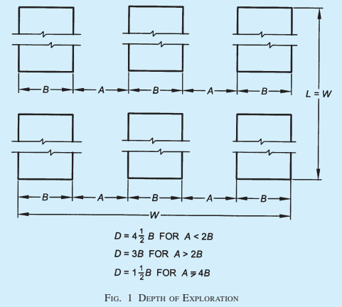
The depth of exploration required depends on the type of proposed structure, its total weight, the size, shape and disposition of the loaded areas, soil profile, and the physical properties of the soil that constitutes each individual stratum. Normally, it should be one and a half times the width of the footing below foundation level. In certain cases, it may be necessary to take at least one bore hole or cone test or both to twice the width of the foundation. If a number of loaded areas are in close proximity the effect of each is additive. In such cases, the whole of the area may be considered as loaded and exploration should be carried out up to one and a half times the lower dimension. In weak soils, the exploration should be continued to a depth at which the loads can be carried by the stratum in question without undesirable settlement and shear failure. In any case, the depth to which seasonal variations affect the soil should be regarded as the minimum depth for the exploration of sites. But where industrial processes affect the soil characteristics this depth may be more. The presence of fast growing and water seeking trees also contributes to the weathering processes.
NOTE — Examples of fast growing and water seeking trees are Banyan (Ficus bengalensis), Pipal (Ficus religiosa) and Neem (Azadirachta indica).
3.2.3.1 An estimate of the variation with depth of the vertical normal stress in the soil arising from foundation loads may be made on the basis of elastic theory. The net loading intensity at any level below a foundation may be obtained approximately by assuming a spread of load of two vertical to one horizontal from all sides of the foundations, due allowance being made for the overlapping effects of load from closely spaced footings. As a general guidance, the depth of exploration at the start of the work may be decided as given in Table 1, which may be modified as exploration proceeds, if required. However, for plant and other main structures, the depth of exploration may be decided depending upon importance of structure, loading conditions and type as well as uniformity of strata.
3.3 Choice of Method for Site Exploration
The choice of the method depends on the following factors.
3.3.1 Nature of Ground
a) Soils — In clayey soils, borings are suitable for deep exploration and pits for shallow exploration. In case of soft sensitive clayey soils field vane shear test may be carried out with advantage.
In sandy soils, special equipments may be required for taking representative samples below the water table. Standard penetration test, dynamic cone penetration test and static cone penetration test are used to assess engineering properties.
b) Gravel-boulder deposits — In the deposits where gravel-boulder proportion is large (>30 percent), the sub-soil strata should be explored by open trial pits of about 5 m × 5 m but in no case less than 2 m × 2 m. The depth of excavation may be up to 6 m. For determining strata characteristics, in-situ tests should be preferred. For shear characteristics and allowable soil pressure dynamic cone penetration tests, load tests on cast in-situ footing and in-situ shear tests that is, boulder-boulder test or concrete-boulder test are more appropriate. For detailed information on these tests reference may be made to good practice [6-2(2)]. Depending on the structure, if required, the strata may be explored by drilling bore hole using suitable method.
c) Rocks — Drillings are suitable in hard rocks and pits in soft rocks. Core borings are suitable for the identification of types of rock, but they cannot supply data on joints and fissures which can be examined only in pits and large diameter borings.
3.3.2 Topography
In hilly country, the choice between vertical openings (for example, borings and trial pits) and horizontal openings (for example, headings) may depend on the geological structure, since steeply inclined strata are most effectively explored by headings and horizontal strata by trial pits or borings. Swamps and areas overlain by water are best explored by borings which may require use of a floating craft.
3.3.3 Cost
For deep exploration, borings are usual, as deep shafts are costly. For shallow exploration in soil, the choice between pits and borings will depend on the nature of the ground and the information required for shallow exploration in rock; the cost of bringing a core drill to the site will be justified only if several holes are required; otherwise, trial pits will be more economical.
Table 1Depth of Exploration (Clause 3.2.3.1)
Sl No.
Type of Foundation
Depth of ExplorationD
(1)
(2)
(3)
i)
Isolated spread footing or raft
3.4 Sampling
3.4.1 Methods of Sampling
a) Disturbed samples — These are taken by methods which modify or destroy the natural structure of the material though with suitable precautions the natural moisture content can be preserved.
b) Undisturbed samples — These are taken by methods which preserve the structure and properties of the material. Such samples are easily obtained from most rocks, but undisturbed samples of soil can be obtained only by special methods. Thin walled tube samples may be used for undisturbed samples in soils of medium strength and tests for the same may be carried out in accordance with good practice [6-2(1)].
NOTE — In case of loose sandy soils and soft soils, specially below water table it may not be possible to take undisturbed sample, in which case other suitable methods may be adopted for exploration.
c) Representative samples — These samples have all their constituent parts preserved, but may or may not be structurally disturbed.
[Clause 3.4.2(a)]
3.4.1.1 The methods usually employed are:
Nature of Ground(1)
Type of Sample(2)
Method of Sampling(3)
Soil
Disturbed
Chunk samplesAuger samples (for example, in clay)Shell samples (for example, in sand)
Undisturbed
Chunk samplesTube samples
Rock
Disturbed
Wash samples from percussion of rotary drilling
Undisturbed
Core barrel sampling
3.4.2 Soil Samples
a) Disturbed soil samples — The mass of sample generally required for testing purposes is given in Table 2.
b) Undisturbed soil samples — The minimum diameter of the sample shall be 38 mm with the minimum length/diameter ratio of 2.
3.4.3 Rock Sample
a) Disturbed samples — The sludge from percussion borings, or from rotary borings which have failed to yield a core, may be taken as a disturbed sample.
b) Undisturbed samples
Block samples — Such samples taken from the rock formation shall be dressed to a size convenient for packing to about 90 mm × 75 mm × 50 mm.
Core sample; see also good practice [6-2(3)]
3.4.4 Protection, Handling and Labelling of Samples
Care should be taken in protecting, handling and subsequent transport of samples and in their full labelling, so that samples can be received in a fit state for examination and testing, and can be correctly recognized as coming from a specified trial pit or boring.
5.2Terminology for Earthquake Engineering of Buildings
5.2.1 For the purpose of earthquake resistant design
of buildings in this standard, the following definitions shall apply:
5.2.2 Base
It is the level at which inertia forces generated in the structure are transferred to the foundation, which then transfers these forces to the ground.
5.2.3 Base Dimensions (d)
Base dimension of the building along a direction is the dimension at its base, in metres, along that direction.
5.2.4 Centre of Mass
The point through which the resultant of the masses of a system acts. This point corresponds to the centre of gravity of masses of system.
5.2.5 Centre of Stiffness
The point through which the resultant of the restoring forces of a system acts.
5.2.6 Design Eccentricity (edi)
It is the value of eccentricity to be used at floor i in torsion calculations for design.
5.2.7 Design Seismic Base Shear (VB)
It is the total design lateral force at the base of a structure.
5.2.8 Diaphragm
It is a horizontal, or nearly horizontal system, which transmits lateral forces to the vertical resisting elements, for example, reinforced concrete floors and horizontal bracing systems.
5.2.9 Dual System
Buildings with dual system consist of shear walls (or braced frames) and moment resisting frames such that:
a) the two systems are designed to resist the total design lateral force in proportion to their lateral stiffness considering the interaction of the dual system at all floor levels; and
b) the moment resisting frames are designed to independently resist at least 25 percent of the design base shear.
5.2.10 Height of Floor (hi)
It is the difference in levels between the base of the building and that of floor i.
5.2.11 Height of Structure (h)
It is the difference in levels, in metres, between its base and its highest level.
5.2.12 Horizontal Bracing System
It is a horizontal truss system that serves the same function as a diaphragm.
5.2.13 Joint
It is the portion of the column that is common to other members, for example, beams, framing into it.
5.2.14 Lateral Force Resisting Element
It is part of the structural system assigned to resist lateral forces.
5.2.15 Moment-Resisting Frame
It is a frame in which members and joints are capable of resisting forces primarily by flexure.
5.2.15.1 Ordinary moment-resisting frame
It is a moment-resisting frame not meeting special detailing requirements for ductile behaviour.
5.2.15.2 Special moment-resisting frame
It is a moment-resisting frame specially detailed to provide ductile behaviour and comply with the requirements given in IS 4326 or IS 13920 or SP 6(6).
5.2.16 Number of Storeys (n)
Number of storeys of a building is the number of levels above the base. This excludes the basement storeys, where basement walls are connected with the ground floor deck or fitted between the building columns. But, it includes the basement storeys, when they are not so connected.
5.2.17 Principal Axes
Principal axes of a building are generally two mutually perpendicular horizontal directions in plan of a building along which the geometry of the building is oriented.
5.2.18 P − Δ Effect
It is the secondary effect on shears and moments of frame members due to action of the vertical loads, interacting with the lateral displacement of building resulting from seismic forces.
5.2.19 Shear Wall
It is a wall designed to resist lateral forces acting in its own plane.
5.2.20 Soft Storey
It is one in which the lateral stiffness is less than 70 percent of that in the storey above or less than 80 percent of the average lateral stiffness of the three storeys above.
5.2.21 Static Eccentricity (esi)
It is the distance between centre of mass and centre of rigidity of floor i.
5.2.22 Storey
It is the space between two adjacent floors.
5.2.23 Storey Drift
It is the displacement of one level relative to the other level above or below.
5.2.24 Storey Shear (V )
It is the sum of design lateral forces at all levels above the storey under consideration.
5.2.25 Weak Storey
It is one in which the storey lateral strength is less than 80 percent of that in the storey above. The storey lateral strength is the total strength of all seismic force resisting elements sharing the storey shear in the considered direction.
7Shallow Foundations
7.0 Design Information
For the satisfactory design of foundations, the following information is necessary:
a) The type and condition of the soil or rock to which the foundation transfers the loads;
b) The general layout of the columns and loadbearing walls showing the estimated loads, including moments and torques due to various loads (dead load, imposed load, wind load, seismic load) coming on the foundation units;
c) The allowable bearing pressure of the soils;
d) The changes in ground water level, drainage and flooding conditions and also the chemical conditions of the subsoil water, particularly with respect to its sulphate content;
e) The behaviour of the buildings, topography and environment/surroundings adjacent to the site, the type and depths of foundations and the bearing pressure assumed; and
f) Seismic zone of the region.
5Materials
5.1 Cement, coarse aggregate, fine aggregate, lime, SURKHI, steel, timber and other materials go into the construction of foundations shall conform to the requirements of Part 5 ‘Building Materials’.
5.2 Protection Against Deterioration of Materials
Where a foundation is to be in contact with soil, water or air, that is, in a condition conducive to the deterioration of the materials of the foundation, protective measures shall be taken to minimize the deterioration of the materials.
5.2.1 Concrete
In the case of concrete placed against a soil containing harmful chemicals (sulphates, chlorides), among other protective measures, it shall be ensured to provide nominal cover required as prescribed in Part 6 ‘Structural Design, Section 5 Concrete for the Applicable Environment Exposure Condition’.
5.2.1.1 Preferably concrete of higher grade shall be used in situations subject to aggressive environment.
5.2.2 Timber
Where timber is exposed to soil, it shall be treated in accordance with good practice [6-2(6)].
7.1Design Considerations
7.1.1 Design Loads
The foundation shall be proportioned for the following combination of loads:
a) Dead load + imposed load; and
b) Dead load + imposed load + wind load or seismic loads, whichever is critical.
For details, reference shall be made to Part 6 ‘Structural Design, Section 1 Loads, Forces and Effects’.
NOTES
1 For load, imposed, wind, seismic and other loads, see Part 6 ‘Structural Design, Section 1 Loads, Forces and Effects’.
2 For coarse grained soils, settlements shall be estimated corresponding to 7.1.1 (b) and for fine grained soils settlement shall be estimated corresponding to permanent loads only.
7.1.2 Allowable Bearing Pressure
The allowable bearing pressure shall be taken as either of the following, whichever is less:
a) The safe bearing capacity on the basis of shear strength characteristics of soil, or
b) The allowable bearing pressure that the soil can take without exceeding the permissible settlement (see 7.1.3).
7.1.2.1 Bearing capacity by calculation
Where the engineering properties of the soil are available, that is, cohesion, angle of internal friction, density, etc the bearing capacity shall be calculated
from stability considerations of shear; factor of safety of 2.5 shall be adopted for safe bearing capacity. The effect of interference of different foundations should be taken into account. The procedure for determining the ultimate bearing capacity and allowable bearing pressure of shallow foundations based on shear and allowable settlement criteria shall be in accordance with good practice [6-2(7)].
7.1.2.2 Field method for determining allowable bearing pressure
Where appropriate, plate load tests can be performed and allowable pressure determined as per good practice [6-2(8)]. The allowable bearing pressure for sandy soils may also be obtained by loading tests. When such tests cannot be done, the allowable bearing pressure for sands may be determined using penetration test.
7.1.2.3 Where the bearing materials directly under a foundation over-lie a stratum having smaller safe bearing capacity, these smaller values shall not be exceeded at the level of such stratum.
7.1.2.4 Effect of wind and seismic force
Where the bearing pressure due to wind is less than 25 percent of that due to dead and live loads, it may be neglected in design. Where this exceeds 25 percent foundations may be so proportioned that the pressure due to combined dead, live and wind loads does not exceed the allowable bearing pressure by more than 25 percent.
When earthquake forces are considered for the computation of design loads, the permissible increase in allowable bearing pressure of pertaining soil shall be as given in Table 3, depending upon the type of foundation of the structure.
7.1.2.5 Bearing capacity of buried strata
If the base of a foundation is close enough to a strata of lower bearing capacity, the latter may fail due to excess pressure transmitted to it from above. Care should be taken to see that the pressure transmitted to the lower strata is within the prescribed safe limits. When the footings are closely spaced, the pressure transmitted to the underlying soil will overlap. In such cases, the pressure in the overlapped zones will have to be considered. With normal foundations, it is sufficiently accurate to estimate the bearing pressure on the underlying layers by assuming the load to be spread at a slope of 2 (vertical) to 1 (horizontal).
7.1.3 Settlement
The permissible values of total and differential settlement for a given type of structure may be taken as given in Table 4. Total settlements of foundation due to net imposed loads shall be estimated in accordance with good practice [6-2(10)]. The following
causes responsible for producing the settlement shall be investigated and taken into account.
a) Causes of settlement
Elastic compression of the foundation and the underlying soil;
Consolidation including secondary compression;
Ground water lowering — Specially repeated lowering and raising of water level in loose granular soils tend to compact the soil and cause settlement of the footings. Prolonged lowering of the water table in fine grained soils may introduce settlement because of the extrusion of water from the voids. Pumping water or draining water by tiles or pipes from granular soils without an adequate mat of filter material as protection may, in a period of time, carry a sufficient amount of fine particles away from the soil and cause settlement;
Seasonal swelling and shrinkage of expansive clays;
Ground movement on earth slope, for example, surface erosion, slow creep or landslides; and
Other causes, such as adjacent excavation, mining, subsidence and underground erosion.
Causes of differential settlements
Geological and physical non-uniformity or anomalies in type, structure, thickness, and density of the soil medium (pockets of sand in clay, clay lenses in sand, wedge like soil strata, that is, lenses in soil), an admixture of organic matter, peat, mud;
Non-uniform pressure distribution from foundation to the soil due to non-uniform loading and incomplete loading of the foundations;
Water regime at the construction site,
Overstressing of soil at adjacent site by heavy structures built next to light ones;
Overlap of stress distribution in soil from adjoining structures;
Unequal expansion of the soil due to excavation for footing;
Non-uniform development of extrusion settlements; and
Non-uniform structural disruptions or disturbance of soil due to freezing and thawing, swelling and softening and drying of soils.
Table 3 Percentage of Permissible Increase in Allowable Bearing Pressure or Resistance of Soils
(Clauses 7.1.2.4 and 8.2.7)
Sl No.
Foundation
Type of Soil Mainly Constituting the Foundation
7.1.4 Depth of Foundations
7.1.4.1 The depth to which foundations should be carried depends upon the following principal factors:
a) The securing of adequate allowable capacity.
b) In the case of clayey soils, penetration below the zone where shrinkage and swelling due to seasonal weather changes, and due to trees and shrubs are likely to cause appreciable movements.
c) In fine sands and silts, penetration below the zone in which trouble may be expected from frost.
d) The maximum depth of scour, wherever relevant, should also be considered and the foundation should be located sufficiently below this depth.
e) Other factors such as ground movements and heat transmitted from the building to the supporting ground may be important.
7.1.4.2 All foundations shall extend to a depth of at least 500 mm below natural ground level. On rock or such other weather resisting natural ground, removal of the top soil may be all that is required. In such cases, the surface shall be cleaned and, if necessary, stepped or otherwise prepared so as to provide a suitable bearing and thus prevent slipping or other unwanted movements.
7.1.4.3 Where there is excavation, ditch pond, water course, filled up ground or similar condition adjoining or adjacent to the subsoil on which the structure is to be erected and which is likely to impair the stability of structure, either the foundation of such structure shall be carried down to a depth beyond the detrimental influence of such conditions, or retaining walls or similar works shall be constructed for the purpose of shielding from their effects.
7.1.4.4 A foundation in any type of soil shall be below the zone significantly weakened by root holes or cavities produced by burrowing animals or works. The depth shall also be enough to prevent the rainwater scouring below the footings.
7.1.4.5 Clay soils, like black cotton soils, are seasonally affected by drying, shrinkage and cracking in dry and hot weather, and by swelling in the following wet weather to a depth which will vary according to the nature of the clay and the climatic condition of the region. It is necessary in these soils, either to place the foundation bearing at such a depth where the effects of seasonal changes are not important or to make the foundation capable of eliminating the undesirable effects due to relative movement by providing flexible type of construction or rigid foundations. Adequate
load counteracting against swelling pressures also provide satisfactory foundations.
7.1.5 Foundation at Different Levels
7.1.5.1 Where footings are adjacent to sloping ground or where the bottoms of the footings of a structure are at different levels or at levels different from those of the footings of adjoining structures, the depth of the footings shall be such that the difference in footing elevations shall be subject to the following limitations:
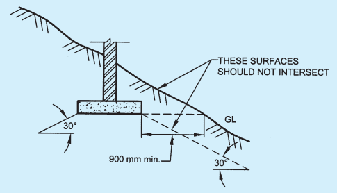
a) When the ground surface slopes downward adjacent to a footing, the sloping surface shall not intersect a frustum of bearing material under the footing having sides which make an angle of 30° with the horizontal for soil and horizontal distance from the lower edge of the footing to the sloping surface shall be at least 600 mm for rock and 900 mm for soil (see Fig. 2).
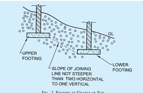
b) In the case of footings in granular soil, a line drawn between the lower adjacent edges of adjacent footings shall not have a steeper slope than one vertical to two horizontal (see Fig. 3).
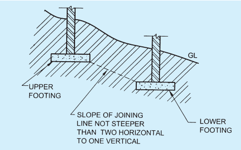
In case of footing of clayey soils a line drawn between the lower adjacent edge of the upper footing and the upper adjacent edge of lower footing shall not have a steeper slope than one vertical to two horizontal (see Fig. 4).
7.1.5.2 The requirement given in 7.1.5.1 shall not apply under the following conditions:
a) Where adequate provision is made for the lateral support (such as, with retaining walls) of the material supporting the higher footing.
b) When the factor of safety of the foundation soil against shearing is not less than four.
7.1.6 Effect of Seasonal Weather Changes
During periods of hot, dry weather a deficiency of water develops near the ground surface and in clay soils, that is associated with a decrease of volume or ground shrinkage and the development of cracks. The shrinkage of clay will be increased by drying effect produced by fast growing and water seeking trees. The range of influence depends on size and number of trees and it increase during dry periods. In general, it is desirable that there shall be a distance of at least 8 m between such trees. Boiler installations, furnaces, kilns, underground cables and refrigeration installations and other artificial sources of heat may also cause increased volume changes of clay by drying out the ground beneath them, the drying out can be to a substantial depth. Special precautions either in the form of
FIG. 2 FOOTING IN SLOPING GROUND
FIG. 3 FOOTING IN GRANULAR SOIL
FIG. 4 FOOTING IN CLAYEY SOIL
insulation or otherwise should be taken. In periods of wet weather, clay soils swell and the cracks lend to close, the water deficiency developed in the previous dry periods may be partially replenished and a subsurface zone or zones deficient in water may persist for many years. Leakage from water mains and underground sewers may also result in large volume changes. Therefore, special care must be taken to prevent such leakages.
7.1.7 Effect of Mass Movements of Ground in Unstable Areas
7.1.7.1 In certain areas mass movements of the ground are liable to occur from causes independent of the loads applied by the foundations of structures. These include mining subsidence, landslides on unstable slopes and creep on clay slopes.
7.1.7.2 Mining subsidence
In mining areas, subsidence of the ground beneath a building or any other structure is liable to occur. The magnitude of the movement and its distribution over the area are likely to be uncertain and attention shall, therefore, be directed to make the foundations and structures sufficiently rigid and strong to withstand the probable worst loading condition.
7.1.7.3 Landslide prone areas
The construction of structures on slopes which are suspected of being unstable and are subject to landslip shall be avoided.
On sloping ground on clay soils, there is always a tendency for the upper layers of soil to move downhill, depending on type of soil, the angle of slope, climatic conditions, etc. In some cases, the uneven surface of the slope on a virgin ground will indicate that the area is subject to small land slips and, therefore, if used for foundation, will obviously necessitate special design consideration.
Where there may be creep of the surface layer of the soil, protection against creep may be obtained by following special design considerations.
On sloping sites, spread foundations shall be on a horizontal bearing and stepped. At all changes of levels, they shall be lapped at the steps for a distance at least equal to the thickness of the foundation or twice the height of the step, whichever is greater. The steps shall not be of greater height than the thickness of the foundation, unless special precautions are taken.
Cuttings, excavations or sloping ground near and below foundation level may increase the possibility of shear failure of the soil. The foundation shall be well beyond the zone of such shear failure.
If the probable failure surface intersects a retaining wall or other revetment, the latter shall be made strong enough to resist any unbalanced thrust. In case of doubt as to the suitability of the natural slopes or cuttings, the structure shall be kept well away from the top of the slopes, or the slopes shall be stabilized.
Cuttings and excavations adjoining foundations reduce stability and increase the likelihood of differential settlement. Their effect should be investigated not only when they exist but also when there is possibility that they are made subsequently.
Where a structure is to be placed on sloping ground, additional complications are introduced. The ground itself, particularly if of clay, may be subject to creep or other forms of instability, which may be enhanced if the strata dip in the same direction as the ground surface. If the slope of the ground is large, the overall stability of the slope and substructure may be affected. These aspects should be carefully investigated.
7.1.8 Precautions for Foundations on Inclined Strata
In the case of inclined strata, if they dip towards a cutting of basement, it may be necessary to carry foundation below the possible slip planes, land drainage also requires special consideration, particularly on the uphill side of a structure to divert the natural flow of water away from the foundations.
7.1.9 Strata of Varying Thickness
Strata of varying thickness, even at appreciable depth, may increase differential settlement. Where necessary, calculations should be made of the estimated settlement from different thickness of strata and the structure should be designed accordingly. When there is large change of thickness of soft strata, the stability of foundation may be affected. Site investigations should, therefore, ensure detection of significant variations in strata thickness.
7.1.10 Layers of Softer Material
Some soils and rocks have thin layers of softer material between layers of harder material, which may not be detected unless thorough investigation is carried out. The softer layers may undergo marked changes in properties if the loading on them is increased or decreased by the proposed construction or affected by related changes in ground water conditions. These should be taken into account.
7.1.11 Spacing Between Existing and New Foundation
The deeper the new foundation and the nearer to the existing it is located, the greater the damage is likely to be. The minimum horizontal spacing between existing and new footings shall be equal to the width of the wider one. While the adoption of such provision
shall help minimizing damage to adjacent foundation, an analysis of bearing capacity and settlement shall be carried out to have an appreciation of the effect on the adjacent existing foundation.
7.1.12 Alterations During Construction
a) Where during construction the soil or rock to which foundation is to transfer loads is found not to be the type or in the condition assumed, the foundation shall be re-designed and constructed for the existing type or conditions and the Authority notified.
b) Where a foundation bears on gravel, sand or silt and where the highest level of the ground water is or likely to be higher than an elevation defined by bearing surface minus the width of the footing, the bearing pressure shall be altered in accordance with Note 4 in Table 3.
c) Where the foundation has not been placed or located as indicated earlier or is damaged or bears on a soil whose properties may be adversely changed by climatic and construction conditions, the error shall be corrected, the damaged portion repaired or the design capacity of the affected foundation recalculated to the satisfaction of the Authority.
d) Where a foundation is placed, and if the results of a load test so indicate, the design of the foundation shall be modified to ensure structural stability of the same.
2.3.12 Multi-Under-Reamed Pile — An under-reamed pile having more than one bulb. The piles having two bulbs may be called double under-reamed piles.
2.3.13 Negative Skin Friction — Negative skin friction is the force developed through the friction between the pile and the soil in such a direction as to increase the loading on the pile, generally due to drag of a consolidating soft layer around the pile resting on a stiffer bearing stratum such that the surrounding soil settles more than the pile.
2.3.14 Ultimate Load Capacity — The maximum load which a pile can carry before failure of ground when the soils fails by shear or failure of pile materials.
2.3.15 Under-Reamed Pile — A bored cast in-situ or bored compaction concrete pile with enlarged bulb(s) made by either cutting or scooping out the soil or by any other suitable process.
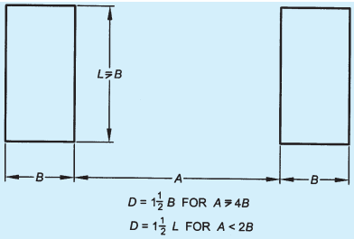
One and a half times the width (B) (see Fig. 1)
ii)
Adjacent footings with clear spacing less than twice the width
One and a half times the length (L) of the footing (see Fig. 1)
iii)
Adjacent rows of footings
See Fig. 1
iv)
Pile and well foundations
To a depth of one and a half times the width of structure from the bearing (toe of pile or bottom of well)
v)
a) Road cuts
Equal to the bottom width of the cut
b) Fill
Two metres below ground level or equal to the height of the fill whichever is greater
3.4.5 Examination and Testing of Samples
3.4.5.1 The following tests shall be carried out in accordance with good practice [6-2(4)].
a) Particle size distribution,
b) Density,
c) Natural moisture content,
d) Consistency limits,
e) Consolidation characteristics,
f) Strength characteristics,
g) Sulphate, chloride and pH content of soil and ground water, and
Table 2Mass of Soil Sample Required
Sl No.
Purpose of Sample
Type
Mass of Sample Required kg
(1)
(2)
(3)
(4)
i)
Soil identification, natural moisture content tests, mechanical analysis, and index properties
Cohesive soil
1
Chemical tests
Sands and gravels
3
ii)
Compaction tests
Cohesive soils and sands
12.5
Gravely soils
25
iii)
Comprehensive examination of construction materials including stabilization
Cohesive soils and sands
25 to 50
Gravely soils
50 to 100
h) Differential free swelling and swelling pressure.
Type I — Rock or Hard Soil: Well graded gravel and sand gravel mixtures with or without clay binder, and clayey sands poorly graded or sand clay mixtures (GB, CW, SB, SW, and SC) ¹⁾ having N²⁾ above 30, where N is the standard penetration value
Type II — Medium Soils: All soils with N between 10 and 30, and poorly graded sands or gravelly sands with little or no fines (SP ¹⁾ ) with N > 15
Type III — Soft Soils: All soils other than SP ¹⁾ with N < 10
(1)
(2)
(3)
(4)
(5)
i)
Piles passing through any soil but resting on soil type I
50
50
50
ii)
Piles not covered under item (i)
—
25
25
iii)
Raft foundations
50
50
50
iv)
Combined isolated RCC footing with tie beams
50
25
25
v)
Isolated RCC footing without tie beams, or unreinforced strip foundations
50
25
—
vi)
Well foundations
50
25
25
1 The allowable bearing pressure shall be determined in accordance with good practice [6-2(7)] and [6-2(8)].
2 If any increase in bearing pressure has already been permitted for forces other than seismic forces, the total increase in allowable bearing pressure when seismic force is also included shall not exceed the limits specified above.
3 Desirable minimum field values of N — If soils of smaller N-values are met, compacting may be adopted to achieve these values or deep pile foundations going to stronger strata should be used.
4 The values of N (corrected values) are at the founding level and the allowable bearing pressure shall be determined in accordance with good practice [6-2(7)] and [6-2(8)].
Seismic Zone Depth Below Ground N Values Remark Level (in m)(1) (2) (3) (4)
≤ 5 15III, IV and V≥ 5 25II ≤ 5 15 (for important structures only) ≥ 10 25
For values of depths between 5 m and 10 m, linear interpolation is recommended
5 The piles should be designed for lateral loads neglecting lateral resistance of soil layers liable to liquefy.
6 Good practice [6-2(5)] and [6-2(9)] may also be referred.
7 Isolated RCC footing without tie beams, or unreinforced strip foundation shall not be permitted in soft soils with N < 10.
See good practice [6-2(5)].
See good practice [6-2(9)].
Sl No.
Type of Structure
Isolated Foundations
Raft Foundations
Sand and Hard Clay
Plastic Clay
Sand and Hard Clay
Plastic Clay
Maximum settlement mm
Differential settlement mm
Angular distortion mm
Maximum settlement mm
Differential settlement mm
Angular distortion mm
Maximum settlement mm
Differential settlement mm
Angular distortion mm
Maximum settlement mm
Differential settlement mm
Angular distortion mm
(1)
(2)
(3)
(4)
(5)
(6)
(7)
(8)
(9)
(10)
(11)
(12)
(13)
(14)
i)
For steel structure
50
.003 3L
1/300
50
.003 3L
1/300
75
.003 3L
1/300
100
.003 3L
1/300
ii)
For reinforced concrete structures
50
.001 5L
1/666
75
.001 5L
1/666
75
.002 1L
1/500
100
.002 0L
1/500
iii)
For multistoreyed buildings
a) RC or steel framed buildings with panel walls
60
.002L
1/500
75
.002L
1/500
75
.002 5L
1/400
125
.003 3L
1/300
b) For load bearing walls
1) L/H = 2*
60
.000 2L
1/5 000
60
.000 2L
1/5000
Not likely to be encountered
2) L/H = 7*
60
.000 4L
1/2 500
60
.000 4L
1/2500
iv)
For water towers and silos
50
.001 5L
1/666
75
.001 5L
1/666
100
.002 5L
1/400
125
.002 5L
1/400
NOTE — The values given in the table may be taken only as a guide and the permissible total settlement/different settlement and tilt (angular distortion) in each case should be decided as per requirements of the designer.
L denotes the length of deflected part of wall/raft or centre-to-centre distance between columns.
H denotes the height of wall from foundation footing.
* For intermediate ratios of L/H, the values can be interpolated.