2.0 For the purpose of this Section, the following definitions shall apply.
2.1 General
2.1.1 Clay — An aggregate of microscopic and sub-microscopic particles derived from the chemical decomposition and disintegration of rock constituents. It is plastic within a moderate to wide range of water content. The particles are less than 0.002 mm in size.
2.1.2 Clay, Firm — A clay which at its natural water content can be moulded by substantial pressure with the fingers and can be excavated with a spade.
2.1.3 Clay, Soft — A clay which at its natural water content can be easily moulded with the fingers and readily excavated.
2.1.4 Clay, Stiff — A clay which at its natural water content cannot be moulded with the fingers and requires a pick or pneumatic spade for its removal.
2.1.5 Foundation — That part of the structure which is in direct contact with and transmits loads to the ground.
2.1.6 Gravel — Cohesionless aggregates of angular rounded or semi-rounded, fragments of more or less unaltered rocks or minerals, 50 percent or more of the particles having size greater than 4.75 mm and less than 80 mm.
2.1.7 Peat — A fibrous mass of organic matter in various stages of decomposition generally dark brown to black in colour and of spongy consistency.
2.1.8 Sand — Cohesionless aggregate of rounded, subrounded, angular, sub-angular or flat fragments of more or less unaltered rock or minerals, 50 percent or more of particles greater than 0.075 mm or less than 4.75 mm in size.
2.1.9 Sand, Coarse — Sand which contains 50 percent or more of particles of size greater than 2 mm and less than 4.75 mm.
2.1.10 Sand, Fine — Sand which contains 50 percent
of particles of size greater than 0.075 mm and less than 0.425 mm.
2.1.11 Sand, Medium — Sand which contains 50 percent of particles of size greater than 0.425 mm and less than 2.0 mm.
2.1.12 Silt — A fine grained soil with little or no plasticity. The size of particles ranges from 0.075 mm to 0.002 mm.
2.1.13 Soft Rock — A rocky cemented material which offers a high resistance to picking up with pick axes and sharp tools but which does not normally require blasting or chiselling for excavation.
2.1.14 Soil, Black Cotton — Inorganic clays of medium to high compressibility. They form a major soil group in India. They are predominately montmorillonitic in structure and yellowish black or blackish grey in colour. They are characterized by high shrinkage and swelling properties.
2.1.15 Soil, Coarse Grained — Soils which include the coarse and largely siliceous and unaltered products of rock weathering. They possess no plasticity and tend to lack cohesion when in dry state.
2.1.16 Soil, Fine Grained — Soils consisting of the fine and altered products of rock weathering, possessing cohesion and plasticity in their natural state, the former even when dry and both even when submerged. In these soils, more than half of the material by weight is smaller than 75-micron IS Sieve size.
2.1.17 Total Settlement — The total downward movement of the foundation unit under load.
2.2 Shallow Foundation
2.2.1 Back Fill — Materials used or re-used to fill an excavation.
2.2.2 Bearing Capacity, Safe — The maximum intensity of loading that the soil will safely carry with a factor of safety without risk of shear failure of soil irrespective of any settlement that may occur.
2.2.3 Bearing Capacity, Ultimate — The intensity of loading at the base of a foundation which would cause shear failure of the supporting soil.
5
2.2.4 Bearing Pressure, Allowable (Gross or Net) — The maximum allowable loading intensity on the ground in any given case (with full cognizance of surcharge) taking into account the maximum safe bearing capacity, the amount and kind of settlement expected and the capability of the structure to take up
this settlement. It is, therefore, a combined function of both the site conditions and characteristics of the particular structure.
The net allowable bearing pressure is the gross allowable bearing pressure minus the surcharge intensity.
NOTE — The concept of ‘gross’ and ‘net’ used in defining the allowable bearing pressure could also be extended to safe bearing capacity, safe bearing pressure and ultimate bearing capacity.
2.2.5 Factor of Safety (with Respect to Bearing Capacity) — A factor by which the ultimate bearing capacity (net) must be reduced to arrive at the value of safe bearing capacity (net).
2.2.6 Footing — A spread constructed in brick work, masonry or concrete under the base of a wall or column for the purpose of distributing the load over a larger area.
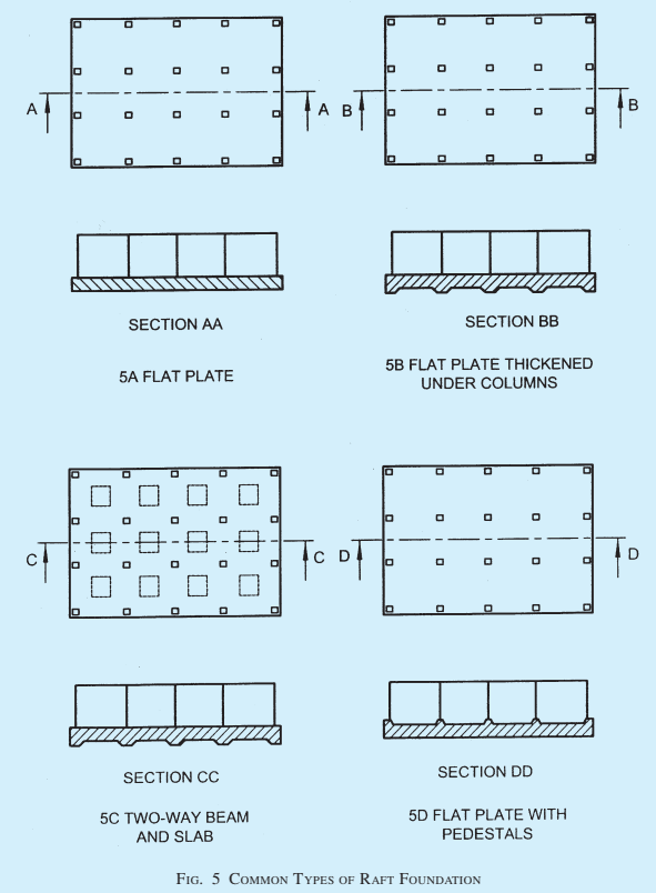
2.2.7 Foundation, Raft — A substructure supporting an arrangement of columns or walls in a row or rows transmitting the loads to the soil by means of a continuous slab, with or without depressions or openings.
2.2.8 Make-up Ground — Refuse, excavated soil or rock deposited for the purpose of filling a depression or raising a site above the natural surface level of the ground.
2.2.9 Offset — The projection of the lower step from the vertical face of the upper step.
2.2.10 Permanent Load — Loads which remain on the structure for a period, or a number of periods, long enough to cause time dependent deformation/ settlement of the soil.
2.2.11 Shallow Foundation — A foundation whose width is generally equal to or greater than its depth.
NOTE — These cover such types of foundations in which load transference is primarily through shear resistance of the bearing strata (the frictional resistance of soil above bearing strata is not taken into consideration) and are laid normally to depth of 3 m.
2.2.12 Spread Foundation — A foundation which transmits the load to the ground through one or more footings.
2.3 Pile Foundation
2.3.1 Batter Pile (Raker Pile) — The pile which is installed at an angle to the vertical.
2.3.2 Bearing Pile — A pile formed in the ground for transmitting the load of a structure to the soil by the resistance developed at its tip and/or along its surface. It may be formed either vertically or at an inclination (Batter Pile) and may be required to take uplift pressure.
If the pile supports the load primarily by resistance developed at the pile point or base, it is referred to as
‘End Bearing Pile’, if support is provided primarily by friction along its surface, it is referred to as ‘Friction Pile’.
2.3.3 Bored Cast in-situ Pile — The pile formed within the ground by excavating or boring a hole within it, with or without the use of a temporary casing and subsequently filling it with plain or reinforced concrete. When the liner is left permanently it is termed as cased pile and when the casing is taken out it is termed as uncased pile.
In installing a bored pile the sides of the borehole (when it does not stand by itself) are required to be stabilized with the aid of a temporary casing, or with the aid of drilling mud of suitable consistency. For marine situations such piles are formed with permanent casing (liner).
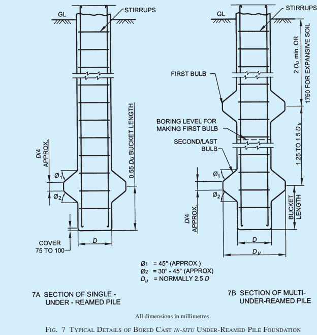
2.3.4 Bored Compaction Pile — A bored cast in-situ pile with or without bulb(s) in which the compaction of the surrounding ground and freshly filled concrete in pile bore is simultaneously achieved by a suitable method. If the pile is with bulb(s), it is known as underreamed bored compaction pile.
2.3.5 Bored Pile — A pile formed with or without casing by excavating or boring a hole in the ground and subsequently filling it with plain or reinforced concrete.
2.3.6 Bored Precast Pile — A pile constructed in reinforced concrete in a casting yard and subsequently lowered in the pre-bored holes and the space around grouted.
2.3.7 Cut-off Level — It is the level where the installed pile is cut-off to connect the pile caps or beams or any other structural components at that level.
2.3.8 Driven Cast in-situ Pile — A pile formed within the ground by driving a casing of permanent or temporary type and subsequently filling in the hole so formed with plain or reinforced concrete. For displacing the subsoil, the casing is installed with a plug or a shoe at the bottom end. When the casing is left permanently, it is termed as cased pile and when the casing is taken out, it termed as uncased pile.
2.3.9 Driven Precast Pile — A pile constructed in concrete (reinforced or prestressed) in a casting yard and subsequently driven in the ground when it has attained sufficient strength.
2.3.10 Efficiency of a Pile Group — It is the ratio of the actual supporting value of a group of piles to the supporting value arrived at by multiplying the pile resistance of an isolated pile by their number in the group.
2.3.11 Factor of Safety — It is the ratio of the ultimate load capacity of a pile to the safe load of a pile.