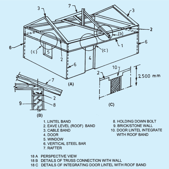
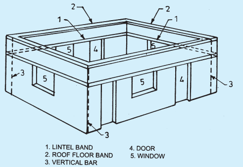
7.6.1 All masonry buildings shall be strengthened by the methods, as specified for various categories of buildings, as listed in Table 15, and detailed in subsequent clauses. Figures 17 and 18 show, schematically, the overall strengthening arrangements to be adopted for category D and E buildings which consist of horizontal bands of reinforcement at critical
| Building Number of Strengthening to be Category Storeys Provided in all Storeys(1) (2) (3) |
|---|
| A i) 1 to 3 a ii) 4 a, b, c B i) 1 to 3 a, b, c, f, g ii) 4 a, b, c, d, f, g C i) 1 and 2 a, b, c, f, g ii) 3 and 4 a to g D i) 1 and 2 a to g ii) 3 and 4 a to h E 1 to 3<sup>1</sup>) a to h where a - Masonry mortar (see 7.3) b - Lintel band (see 7.6.2) c - Roof band and gable band where necessary (see 7.6.3 and 7.6.4), d - Vertical steel at corners and junctions of walls (see 7.6.8) e - Vertical steel at jambs of openings (see 7.6.9) f - Bracing in plan at tie level of roofs g - Plinth band where necessary (see 7.6.6), and h - Dowel bars (see 7.6.7) <sup>1</sup>) Fourth storey not allowed in category E. NOTE - In case of four storey buildings of category B, the requirements of vertical steel may be checked through a seismic analysis using a design seismic coefficient equal to four times the one given in good practice [6-4(8)] (this is because the brittle behaviour of masonry in the absence of a vertical steel results in much higher effective seismic force than that envisaged in the seismic coefficient, provided in the Code). If this analysis shows that vertical steel is not required the designer may take the decision accordingly. |
levels, vertical reinforcing bars at corners, junctions of walls and jambs of opening.
7.6.2 Lintel band is a band provided at lintel level on all load bearing internal, external longitudinal and cross walls. The specifications of the band are given in 7.6.3.
NOTE — Lintel band if provided in panel or partition walls also will improve their stability during severe earthquake.
7.6.3 Roof band is a band provided immediately below the roof or floors. The specifications of the band are given in 7.6.5. Such a band need not be provided underneath reinforced concrete or brick-work slabs resting on bearing walls, provided that the slabs are continuous over the intermediate wall up to the crumple sections, if any, and cover the width of end walls, fully or at least ¾ of the wall thickness.
7.6.4 Gable band is a band provided at the top of gable masonry below the purlins. The specifications of the band are given in 7.6.5. This band shall be made continuous with the roof band at the eaves level.
7.6.5 Section and Reinforcement of Band
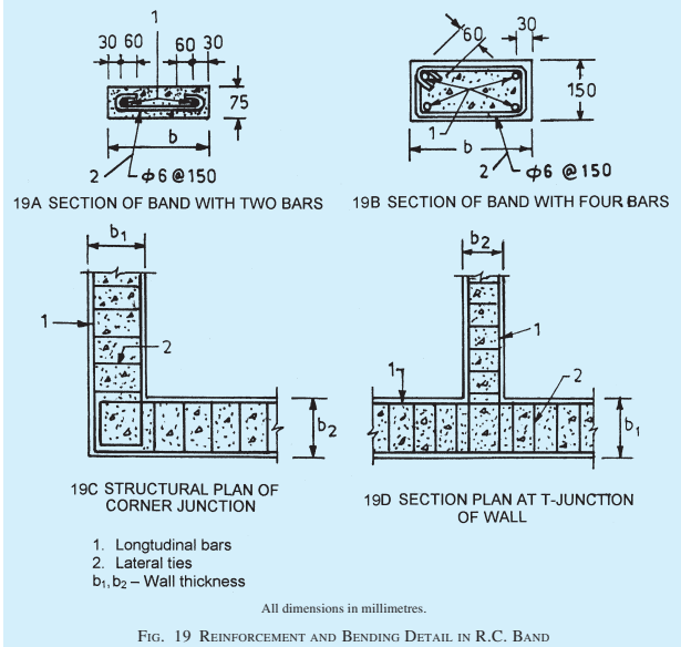
The band shall be made of reinforced concrete of grade not leaner than M15 or reinforced brick work in cement mortar not leaner than 1:3. The bands shall be of the full width of the wall, not less than 75 mm in depth and reinforced with steel, as indicated in Table 16.
NOTE — In coastal areas, the concrete grade shall be M20 concrete and the filling mortar of 1:3 (cement sand with water proofing admixture).
| Span | Building Category | Building Category | Building Category | Building Category | ||||
| B | C | D | E | |||||
| No. of Bars | Dia | No. of Bars | Dia | No. of Bars | Dia | No. of Bars | Dia | |
| m(1) | mm(2) | (4) | mm(5) | mm(6) | (8) | mm(9) | ||
| 5 or less | 2 | 8 | 2 | 8 | 2 | 8 | 2 | 10 |
| 6 | 2 | 8 | 2 | 8 | 2 | 10 | 2 | 12 |
| 7 | 2 | 8 | 2 | 10 | 2 | 12 | 4 | 10 |
| 8 | 2 | 10 | 2 | 12 | 4 | 10 | 4 | 12 |
| NOTES | ||||||||
| 1 Span of wall will be the distance between centre lines of its cross walls or buttresses. For spans greater than 8 m it will be desirable to insert pilasters or buttresses to reduce the span or special calculations shall be made to determine the strength of wall and section of band. | ||||||||
| 2 The number and diameter of bars given above pertain to high strength deformed bars. If plain mild steel bars are used keeping the same number, the following diameters may be used: | ||||||||
| High strength deformedsteel bar diameter | 8 | 10 | 12 | 16 20 | ||||
7.6.8 Vertical Reinforcement
Vertical steel at corners and junctions of walls, which are up to 340 mm (1½ brick) thick, shall be provided as specified in Table 17. For walls thicker than 340 mm, the area of the bars shall be proportionately increased.
| No. of Storeys | Storey | Diameter of HSD Single Bar in mm at Each Critical Section | |||
| Category B | Category C | Category D | Category E | ||
| (1) | (2) | (3) | (4) | (5) | (6) |
| One | — | Nil | Nil | 10 | 12 |
| Two | Top | Nil | Nil | 10 | 12 |
| Bottom | Nil | Nil | 12 | 16 | |
| Three | Top | Nil | 10 | 10 | 12 |
| Middle | Nil | 10 | 12 | 16 | |
| Bottom | Nil | 12 | 12 | 16 | |
| Four | Top | 10 | 10 | 10 | |
| Third | 10 | 10 | 12 | Four storeyed building not permitted | |
| Second | 10 | 12 | 16 | ||
| Bottom | 12 | 12 | 20 | ||
| NOTES | |||||
| 1 The diameters given above are for high strength deformed steel bars. For mild steel plain bars, use equivalent diameters as given in Table 16 (Note 2). | |||||
| 2 The vertical bars will be covered with concrete M 15 or mortar 1:3 grade in suitably created pockets around the bars. This will ensure their safety from corrosion and good bond with masonry. | |||||
| 3 In case of floors/roofs with small precast components, also refer good practice [6-4(8)] for floor/roof band details. | |||||
For earthquake resistant framed wall construction, (see 7.7). No vertical steel need be provided in category A buildings.