This Section covers requirements and guidelines regarding planning against noise, acceptable noise levels and the requirements for sound insulation in buildings with different occupancies.
Loading…
2.0 For the purpose of this Section, the following definitions shall apply.
2.1 Ambient Noise — The sound pressure levels associated with a given environment. Ambient noise is usually a composite of sounds from near and far sources none of which are particularly dominant.
2.2 Audible Frequency Range — The range of sound frequencies normally heard by the human ear. The audible range spans from 20 Hz to 20 000 Hz.
2.3 A-Weighted Sound Pressure, p — Value of p A overall sound pressure, measured in pascals (Pa), after the electrical signal derived from a microphone has been pased through an A-weighting network.
NOTE — The A-weighting network modifies the electrical response of a sound level meter with frequency in approximately the same way as the sensitivity of the human hearing system.
2.4 A-Weighted Sound Pressure Level, L p A - Quantity of A-weighted sound pressure, given by the following formula in decibels (dBA):
where
p A = is the A-weighted sound pressure in pascals (Pa); and
p o = is the reference sound pressure (20 μ Pa).
NOTE — Measurements of A-weighted sound pressure level can be made with a meter and correlate roughly with subjective assessments of loudness, and are usually made to assist in judging the effects of noise on people. The size of A-weighting in 1/3 octave bands, is shown in Annex A (see A-5). An increase or decrease in level of 10 dBA corresponds roughly to a doubling or halving of loudness.
2.5 Background Noise — The sound pressure levels in a given environment from all sources excluding a specific sound source being investigated or measured.
2.6 Break-in — Unwanted sound transmission into a duct from outside.
2.7 Break-out — Unwanted sound transmission from inside a duct to the outside.
5
2.8 Broad Band Noise — Spectrum consisting of a large number of frequency components, none of which is individually dominant.
2.9 Cross-Talk — Unwanted sound transmission between one room and another room or space via a duct.
2.10 Decibels — Ten times the logarithm (to the base 10) of the ratio of two mean square values of sound pressure, sound power or sound intensity. The abbreviation for ‘decibels’ is dB.
2.11 Effective Perceived Noise Level in Decibel (EPN dB) — The number for rating the noise of an individual aircraft flying overhead is the effective perceived noise level in decibels (EPN dB). The effective perceived noise decibel value takes into account the subjectively annoying effects of the noise including pure tones and duration. In principle, it is a kind of time-integrated loudness level.
2.12 Equivalent Continuous A-Weighted Sound Pressure Level, L A e q . T — Value of the A-weighted sound pressure level in decibels (dB) of a continuous, steady sound, that within a specified time interval, T, has the same mean squared sound pressure as the sound under consideration that varies with time, given by the formula:
where
p A ( t ) = is the instantaneous A-weighted sound pressure in pascals (Pa); and
p _ 0 = is the reference sound pressure (20 μ Pa).
NOTE — Equivalent continuous A-weighted sound pressure level is mainly used for the assessment of environmental noise and occupational noise exposure.
2.13 Equivalent Sound Absorption Area of a Room, A — Hypothetical area of a totally absorbing surface without diffraction effects, expressed in square metres (m2) which, if it were the only absorbing element in the room, would give the same reverberation time as the room under consideration.
2.14 Facade Level — Sound pressure level measured 1 m to 2 m in front of the façade.
NOTE — Facade level measurements of L _ p A are usually 2 dB to 3 dB higher than corresponding free-field measurements.
To reduce the transmission of air-borne noise, sound insulating materials may be used. Sound insulating materials block the passage of noise through them by virtue of their mass and physical properties. The extent of noise reduction provided by a single homogeneous panel is proportional to the logarithm of mass per unit area. For high values of sound insulation, normally heavy panels are required. Thin sheets of materials do not have adequate mass for providing any appreciable sound transmission loss by themselves. However, when thin sheet materials are used in a double panel construction with an intervening air cavity, this special construction can give extremely high sound transmission loss values considering the mass of the partition, if designed properly. Porous materials lack the mass required to provide any appreciable sound transmission loss, and readily allow sound at most frequencies to be transmitted through them.
To reduce the transmission of structure-borne noise (such as, noise generated by impacts) special construction methods and elastic discontinuity in the structure may be used. Structure-borne noise reduction is effected by corner joints, changes in cross-section, changes in materials, etc, in construction. The reduction by these construction methods is, however, not appreciable specially when a large amount of noise reduction is required over a short distance. In such cases, introduction of an elastic discontinuity in the structure can result in a very large amount of noise reduction. The noise transmission is affected only above a certain lower frequency which depends on the material thickness and the elastic properties of the material. Bonded fibrous materials, rubber elastomers, cork, etc, are suitable for curtailing structure-borne noise transmission.
This Section is largely based on the following standards:
IS 1950 : 1962 Code of practice for sound insulation of non-industrial buildings
IS 3483 : 1965 Code of practice for noise reduction in industrial buildings
IS 4954 : 1968 Recommendations for noise abatement in town planning
IS 11050 Rating of sound insulation in buildings and of building elements:
(Part 1) : 1984 Airborne sound insulation in buildings and of interior building elements
(Part 2) : 1984 Impact sound insulation
BS 8233 : 1999 Code of practice for sound insulation and noise reduction for buildings
In this revision, opportunity has been taken to update all references to relevant Indian Standards referred to in the text.
All standards, whether given herein above or cross-referred to in the main text of this Section, are subject to revision. The parties to agreement based on this Section are encouraged to investigate the possibility of applying the most recent editions of the standards.
NOTE — Measurements made 1.2 m to 1.5 m above the ground and at least 3.5 m away from other reflecting surfaces are usually regarded as being free-field measurements. To minimize the effect of reflections the measuring position should be at least 3.5 m to the side of the reflecting surface (that is, not 3.5 m from the reflecting surface in the direction of the source). Estimates of noise from aircraft overhead usually include a correction of 2 dB to allow for reflections from the ground.
2.16 Frequency — The number of cyclical variations per unit time. Frequency is generally expressed in cycles per second (cps) and is also denoted as Hertz (Hz).
2.17 Impact Sound Pressure Level, L i ~ — ~ A v e r a g e sound pressure level in a specific frequency band in a room below a floor, when it is excited by a standard tapping machine.
2.18 Indoor Ambient Noise — Pervasive noise in a given situation at a given time, usually composed of noise from many sources, inside and outside the building, but excluding noise from activities of the occupants.
Insertion loss is generally defined as the difference, in decibels, between two sound pressure levels (or power levels or intensity levels) which are measured at the same point in space before and after a muffler or any other noise control device is inserted between the measurement point and the noise source.
2.20 Noise — Unwanted sound which may be hazardous to health, intrerferes with communications or is disturbing.
2.21 Noise Exposure Forecast (NEF) — The noise exposure forecast at any location is the summation of the noise levels in EPN dB from all aircraft types, on all runways, suitably weighted for the number of operations during day time and night time.
2.22 Noise Rating (NR) — Graphical method for rating a noise by comparing the noise spectrum with a family of noise rating curves.
NOTE — Noise rating is described in Annex C.
A single figure descriptor of the sound absorption property of a material. It is the arithmetic mean of the sound absorption co-efficients at 250, 500, 1 000 and 2 000 Hz rounded off to the nearest multiple of 0.05.
2.24 Normalized Impact Sound Pressure Level, L n — Impact sound pressure level normalized for a standard absorption area in the receiving room.
NOTE — Normalized impact sound pressure level is usually used to characterize the insulation of a floor in a laboratory against impact sound in a stated frequency band (see Annex B).
2.25 Octave Band — Band of frequencies in which the upper limit of the band is twice the frequency of the lower limit.
2.26 Percentile Level, L A N , T - A -weighted sound pressure level obtained using time-weighting ° F which is exceeded for N percent of a specified time interval.
Example:
L A 9 0 , 1 h is the A-weighted level exceeded for 90 percent of 1 h. Percentile levels determined over a certain time interval cannot accurately be extrapolated to other time intervals. Timeweighting F ~ o r ~ S can be selected on most modern measuring instruments and used to determine the speed at which the instrument responds to changes in the amplitude of the signal. Time-weighting ° F ′ is faster than ° S ′ and so its use can lead to higher values when rapidly changing signals are measured.
2.27 Pink Noise — Sound with an uninterrupted frequency spectrum and a power which is steady within frequency band and proportional to centre frequency. An example is constant power level per octave band.
2.28 Pure Tone — A sound emitted at a single frequency.
2.29 Rating Level, L A r , T r — Equivalent continuous A-weighted sound pressure level of the noise, plus any adjustment for the characteristic features of the noise.
NOTE — This definition is used for rating industrial noise, where the noise is the specific noise from the source under investigation.
2.30 Reverberation Time, T — Time that would be required for the sound pressure level to decrease by 60 dB after the sound source has stopped.
NOTE — Reverberation time is usually measured in octave or third octave bands. It is not necessary to measure the decay over the full 60 dB range. The decay measured over the range 5 dB to 35 dB below the initial level is denoted by T 3 0 ° and over the range 5 dB to 25 dB below the initial level by T 2 0 °
2.31 Sound — A vibrational disturbance, exciting hearing mechanisms, transmitted in a predictable manner determined by the medium through which it propagates. To be audible the disturbance shall have to fall within the frequency range of 20 Hz to 20 000 Hz.
2.32 Sound Exposure Level, L A E - Level of a sound, of 1 s duration, that has the same sound energy as the actual noise event considered.
NOTES
1 The L A E of a discrete noise event is given by the formula:
where
P (t) = is the instantaneous A-weighted sound pressure in pascals (Pa);
t 2 – t 1 = is a stated time interval in seconds (s) long enough to encompass all significant sound energy of the event;
p o = is the reference sound pressure level (20μ Pa); and
t o = is the reference time interval (1 s).
2 L A E is also known as L A X (single-event noise exposure level).
2.33 Sound Power — The acoustic power of a sound source, expressed in Watts.
2.34 Sound Power Level, L w — The acoustic power radiated from a given sound source as related to a reference power level (typically 1 0 - 1 2 watts) and expressed in decibels as:
where
W = Acoustic power in watts.
By definition, 1 W therefore corresponds to 120 dB for L w
2.35 Sound Pressure, p — Root-mean-square value of the variation in air pressure measured in pascals (Pa), above and below atmospheric pressure, caused by the sound.
2.36 Sound Pressure Level, L p - Quantity of sound pressure, in decibels (dB), given by the formula:
where
p = is the root mean square sound pressure in pascals (Pa); and
p o = is the reference sound pressure (20μ Pa).
NOTE — The range of sound pressures for ordinary sounds is very wide. The use of decibels gives a smaller, more convenient range of numbers. For example, sound pressure levels ranging from 40 dB to 94 dB correspond to sound pressures ranging from 0.002 Pa to 1 Pa. A doubling of sound energy corresponds to an increase in level of 3 dB.
2.37 Sound Receiver — One or more observation points at which sound is evaluated or measured. The effect of sound on an individual receiver is usually evaluated by measurements near the ear or close to the body.
2.38 Sound Reduction Index, R — Laboratory measure of the sound insulating properties of a material or building element in a stated frequency band.
NOTE — For further information see Annex B.
2.39 Sound Source — Equipment or phenomena which generate sound. Source room is the room containing sound source.
2.40 Spectrum — A quantity expressed as a function of frequency, such as sound pressure versus frequency curve.
2.41 Standardized Impact Sound Pressure Level, L n T - Impact sound pressure level normalized to a reverberation time in the receiving room of 0.5 s.
NOTE — Standardized impact sound pressure level is used to characterize the insulation of floors in buildings against impact sound in a stated frequency band (see Annex B).
2.42 Speech Interference Level (SIL) — A descriptor for rating steady noise according to its ability to interfere with conversation between two people. SIL is the arithmetic average of the sound pressure levels in the three octave bands with centre frequencies at 500, 1 000 and 2 000 Hz.
2.43 Standardized Level Difference, D n T Difference in sound level between a pair of rooms, in a stated frequency band, normalized to a reverberation time of 0.5 s.
NOTE — Standardized level difference takes account of all sound transmission paths between the rooms (see Annex B).
2.44 Structure Borne Noise — Generation and propagation of time dependent motions and forces in solid materials which result in unwanted radiated sound.
2.45 Transient Sound — Sound which is audible for a limited period of time, for example sound from over flight of an airplane.
2.46 Third Octave Band — Band of frequencies in which the upper limit of the band is 2 ~ ~ 1 / 3 ~ times the frequency of the lower limit.
2.47 Threshold of Hearing — The lowest continuous sound pressure level which will create an auditory sensation for the average human ear. Any sound below these levels will be inaudible and any sound above the threshold will vary in loudness dependent on intensity.
2.48 Vibration Isolation — Reduction of force or displacement transmitted by a vibratory source, often attained by use of a resilient mount.
2.49 Wavelength — The length in space of one complete cycle of a sound wave.
2.50 Weighted Level Difference, D w — Singlenumber quantity that characterizes airborne sound insulation between rooms but which is not adjusted to reference conditions.
NOTE — Weighted level difference is used to characterize the insulation between rooms in a building as they are; values cannot normally be compared with measurements made under other conditions {see good practice [8-4(1)]}.
2.51 Weighted Sound Reduction Index, R _ w - Single number quantity which characterizes the airborne sound insulating properties of a material or building element over a range of frequencies.
NOTE — The weighted sound reduction index is used to characterize the insulation of a material or product that has been measured in a laboratory (see Annex B).
2.52 Weighted Standardized Impact Sound Pressure Level, L ~ n T , ~ w ~ - ~ ' Single number quantity used to characterize the impact sound insulation of floors over a range of frequencies.
NOTE — Weighted standardized impact sound pressure level is used to characterize the insulation of floors in buildings (see Annex B).
2.53 Weighted Standardized Level Difference, D n , T w Single-number quantity, which characterizes the airborne sound insulation between rooms
NOTE — Weighted standardized level difference is used to characterize the insulation between rooms in a building (see Annex B).
2.54 Weighted Normalized Impact Sound Pressure Level, L n , w ' — Single number quantity used to characterize the impact sound insulation of floors over a range of frequencies.
NOTE — Weighted normalized impact sound pressure level is usually used to characterize the insulation of floors tested in a laboratory (see Annex B).
2.55 White Noise — A noise whose spectrum (level) density is substantially independent of frequency over a specified range and has equal power for any range of frequencies of constant band width.
3 PLANNING AND DESIGN AGAINST OUTDOOR NOISE
Planning against noise should be an integral part of town and country planning proposals, ranging from regional proposals to detailed zoning, and threedimensional layouts and road design within built-up areas. Noise nuisance should be fully recognized in zoning regulations.
3.1.1 Noise is either generated by traffic (road, rail and underground railway) or it arises from zones and buildings within built-up areas (industry, commerce, offices and public buildings). For planning, the noise
survey should examine all the possible causes of noise and consider the various factors causing actual nuisance.
3.1.2 Noise by night, causing disturbance of sleep, is more of nuisance than noise by day. For this reason, housing colonies that adjoin areas with heavy traffic movement during the night are liable to cause serious complaints. Also, the factories that work by night are liable to cause serious complaints if housing estates adjoin them. While planning, care should be taken that housing colonies are adequately setback from busy airports, state and national highways, factories, main railway lines and marshalling yards.
3.1.3 There are two aspects of defence by planning. The first is to plan so as to keep the noise at a distance. Under this aspect comes the separation of housing from traffic noise by interposing buffer zones, and the protection of schools and hospitals by green belts, public gardens, etc. The second is the principle of shading or screening. This consists of deliberately interposing a less vulnerable building to screen a more vulnerable one or by providing a solid barrier, such as a wall, between the source and the location to be protected.
For guidance, approximate noise levels due to various types of aircrafts, measured on ground, when the aircrafts fly overhead at a height of 450 m, are given in Table 1.
| Sl Type of Aircraft Flyover Noise Levels at 450 m No. with Take-off Thrust (EPN dB)(1) (2) (3) |
|---|
| i) Boeing 737 107 ii) Boeing 747-200 103 iii) Airbus A 300 101 iv) Concorde SST 114 |
Noise levels of some typical railway traffic are given in Table 2.
| Sl Type of Train Noise Level at 30 m, Measured No. on the Side or in the Direction of Train, dB (A)(1) (2) (3) |
|---|
| i) Steam train, 60 km/h 85 ii) Diesel train, 60 km/h 83 iii) Electric train, 60 km/h 77 |
The level of noise generated by road traffic depends upon such factors as the number of vehicles passing per hour, the type of traffic, the preponderance of heavy vehicles, average speed, gradient and smoothness of traffic flow. The smoothness of traffic flow also affects variability of the noise and is governed by such things as roundabouts and traffic lights, and the volume of traffic and pedestrian movement with their effects on stopping, starting and overtaking. The level of traffic noise fluctuates continuously and the way it does has a considerable effect on the nuisance caused. For assessing traffic noise, noise is measured in dB(A). Because of the fluctuating nature of traffic, noise levels due to different volumes of traffic flow with a varying mix of vehicles are given in Table 3.
| Sl No. | Type of Traffic | L₁₀ 30 m from Edge of Road, dB(A) |
| (1) | (2) | (3) |
| i) | 5 000 vehicles per 18 hour day (10 percent heavy vehicles), 50 kmph | 65 |
| ii) | 10 000 vehicles per 18 hour day (20 percent heavy vehicles), 60 kmph | 70 |
| iii) | 10 000 vehicles per 18 hour day (40 percent heavy vehicles), 80 kmph | 75 |
| iv) | 20 000 vehicles per 18 hour day (40 percent heavy vehicles), 80 kmph | 77 |
| NOTE — The values are applicable to free flowing traffic without honking. | ||
The outdoor noise regulations in force from time-to-time shall be complied with (see also Annex D).
Near airports two sources of aircraft noise should be considered.
a) Flyover noise — Flyover noise is that which occurs under flight paths close to airports and is the most serious and common problem. As the aircraft passes overhead the noise level at any particular location rises to a peak and then decreases.
b) Ground noise — The noise emitted by an aircraft during ground operations is less variable in direction than flyover noise, but is usually of a longer duration.
3.4.1.1 Aircraft noise may disturb sleep, rest and communication, and as such may be considered
potentially harmful to health. It is important that no new development is carried out within areas where the expected noise levels will cause mental and physical fatigue or permanent loss of hearing. In case development in such areas is essential, adequate sound insulation shall be provided for the building.
3.4.1.2 As the problems caused by aircraft noise have become more acute, a number of methods have been devised for evaluating noise exposure in the vicinity of airports. They all combine many factors into a single number evaluation. A commonly used criterion is the noise exposure forecast (NEF). The NEF is used primarily to develop noise contours for areas around airports. It has been accepted generally that noise exposure forecast levels greater than NEF 40 are unacceptable to people while levels less than NEF 25 are normally acceptable.
3.4.1.3 While it is theoretically possible to provide sufficient insulation to achieve an acceptable indoor noise environment in the area of very high outdoor noise, there is a level above which aircraft noise seriously affects living conditions no matter how much sound insulation has been applied to the dwelling unit. For this reason it is recommended that no residential development be allowed beyond the NEF 35 level.
3.4.1.4 During summer months, the windows are normally kept open for adequate ventilation. In view of this, no matter how much sound insulation is provided for the building structure, the noise level inside the room can never be less than 10 dB below the outdoor noise level. For very critical buildings, such as buildings necessary for maintaining and supplementing the airport services, and for commercial development, such as hotels, it is possible to provide sealed windows and to centrally air-condition the entire building. However, it is not feasible for most of the residential developments in the country. In such cases proper zoning regulations and siting of vulnerable buildings away from aircraft noise are of vital importance.
This is a very serious source of noise in built-up areas, both by day and by night. Railway cuttings reduce the spread of noise, whereas embankments extend it. The elevated railway on viaducts or embankment is very common in built-up areas. The elevation increases exposure to noise but in addition the construction of the viaduct may effect the propagation of noise. In this respect solid embankments are preferable to built-up arches, which tend to act as sound boxes. Worst of all are the steel bridges, which greatly magnify the noise due to vibration. Uphill gradients are another feature tending to increase noise, especially of heavy goods trains.
3.4.2.1 Wherever possible, no residential or public building zone should abut onto railway lines, especially on the marshalling yards which is particularly objectionable because of the shrill, clanging and intermittent noise they generate, often at night. The appropriate zones along side railway lines are industrial and commercial buildings other than office buildings. Where these precautions are not practicable and housing has to abut on to railway lines, every attempt may be made to house as few people as possible in the vicinity of the railway lines.
3.4.2.2 Underground transportation system can be a major cause of disturbance for the neighbouring community. Very high noise levels are propagated to long distances by the underground high speed railway, as a result of wheel rail interaction. Both air-borne noise and ground or structure-borne vibration are potential sources of complaints. Noise control measures, therefore, need to be considered for the following:
a) In stations, where high noise levels are produced at the arrival and departure of trains;
b) In tunnels, during high speed train movement;
c) Where an underground rail transit system passes close to existing structures or high rise buildings adequate attention should also be paid to the problem of ground vibration transmitted to the building, and proper isolation should be provided for critical areas;
d) Wherever elevated railway tracks are provided, adequate measures should be taken to avoid the spread of noise in the surrounding built up areas; and
e) In transit cars, where sound insulation is of vital importance to provide comfortable conditions for the commuters.
3.4.3.1 Convoys of long distance heavy trucks at night moving past through built-up areas cause serious noise complaints. On busy roads, the noise of continuous traffic may be a worse nuisance than that of railways. At least the same precautions may, therefore, be taken in the planning of dwellings in relation to arterial and trunk roads as with railways. Care may be taken that local housing roads do not provide short cuts for heavy traffic through residential areas. Hilly roads present the additional noise of gear changing. Trees with heavy foliage planted on both sides of carriageway help slightly to muffle the noise, provided the foliage extends for a considerable distance (30 m or above).
3.4.3.2 Road traffic may give rise to serious nuisance particularly on busy thorough fares, between continuous high buildings in main streets, at the traffic
lights, near bus stops, on steep slopes and in parking spaces and enclosed yards.
3.4.3.3 For zoning and planning new buildings in urban areas it is recommended that external L A 1 0 is limited to a maximum of 70 dB(A) when the dwellings are proposed to have sealed windows and 60 dB(A) when the dwellings are proposed to have open windows. Indeed it is desirable to confine major new residential development to locations subject to L A 1 0 levels substantially lower than those given above.
It is recognized, however, that within the large urban areas, the use of sites where the external L A 1 0 is greater than 60-70 dB(A) can not always be avoided. In that case it is suggested to utilize such design solutions as barrier blocks in order to reduce external L A 1 0 noise levels to at least 60-70 dB(A) at any point 1.0 m from any inward looking façade. When the orientation of site and the density of development are such that this cannot be fully achieved some form of dwelling insulation will have to be provided. It should be appreciated that where open windows are a must, the occupants would have to put up with discomfort if the above conditions are not met.
3.4.3.4 Certain other methods can often be utilized to provide economical and effective protection from noise:
a) Methods may be adopted to improve the smoothness of flow and reduce number of stopping and starting. This leads to an improvement even if it leads to increased flows. Flow linking of traffic lights, for example, may reduce noise nuisance.
b) Use of roads passing through residential areas may be prohibited to heavy commercial vehicles. An alternative would be to limit use by commercial vehicles to certain times of the day.
c) Use of honking may be prohibited near sensitive buildings, such as hospitals and the like.
d) Barriers may be provided to shield sites from noise.
The zoning of the different cities shall be done by the town planning authorities, taking into account besides other aspects, the noise levels from different occupancies. Wherever necessary, experts in the field may be consulted. For detailed information on noise reduction for town planning schemes, reference may be made to good practice [8-4(2)].
Where relief from noise is to be provided by means of
green belts these may be of considerable width and be landscaped. (In case of railway tracks, a minimum distance of 50 m to 70 m may be provided between the buildings and the tracks.) The extent of relief that may be derived from the above may be estimated only after considering other environmental factors. Only thick belts of planting (greater than 30 m) are of real value. Strong leafy trees may be planted to act as noise baffles. Shrubs or creepers may also be planted for additional protection between tree trunks; artificial mounds and banks should be formed where practicable. As little hard paving and as much grass as possible may be used. The creation of green belt is particularly advisable on the perimeter of aerodromes, along railway lines and arterial roads, through or past builtup areas and adjoining noisy industrial zones.
Barriers are often the most effective means of reducing traffic noise around residential areas. They have the great advantage that they generally protect most or all of the site. In nearly all situations, a well-designed barrier of even a modest height (say 3 m) can at least ensure that all areas of open space are free from excessive noise levels.
There are two types of barriers that can be built to protect sites; one which are built solely for the purpose of reducing noise and two, which form part of the building complex (barrier blocks). Free standing walls and artificial mounds are typical examples of the first type while single and multi-storeyed dwellings and/or garages are the most common form of the second.
Of the two types, barrier blocks are more widely used because they are cheaper and also tend to form a more effective barrier overall because of their greater height and width. Barrier walls or mounds are more limited in their effect than barrier blocks for they protect little more than the area of the site close to ground level essentially because of the lack of height, as continuous walls much higher than 3 m are often difficult to construct.
The purpose of noise control is to ensure that people are neither harmed not disturbed by noise. In addition to provisions given in this Section, special advice may be required for more complex situations, such as those listed in Annex E.
The main sources of outdoor noise in residential areas are traffic (aeroplane, railways, roadways), children playing, hawkers, services deliveries, road repairs
blaring loud-speakers and various types of moving machinery in the neighbourhood and building operations.
5.1.2.1 As far as indoor noises are concerned, conversation of the occupants, footsteps, banging of doors, shifting of the furniture, operation of the cistern and water closet, playing of radio, television, music system, cooling and ventilation machinery, etc, contribute most of the noise emanating from an adjacent room or an adjacent building. Noise conditions vary from time-to-time and noise which may not be objectionable during the day may assume annoying proportions in the silence of the night when quiet conditions are essential.
5.1.2.2 In the case of flats the main sources of noise are from other flats and from stairs, lifts and access balconies. Plumbing noise is another cause. In semi-detached buildings, outdoor noises from streets are noticed more than indoor noises from neighbours.
The most desirable method is to locate the residential buildings in a quiet area away from the noisy sources like the industrial areas, rail tracks, aerodromes, roads carrying heavy traffic, etc.
5.2.1.1 To minimize ground reflection, the dwellings should be surrounded by the maximum amount of planting and grassed areas and the minimum amount of hard surfacing. This applies particularly to high density areas. Where for maintenance reasons a large amount of hard paving is necessary, it should be broken up by areas of planting and grassing. Narrow hard paved courts should be avoided between adjacent tall buildings.
5.2.1.2 Roads within a residential area should be kept to a minimum both in width and length, and should be designed to discourage speeding. Area-wise planning, with zones from which vehicular traffic is altogether excluded will greatly help to reduce noise. Roads with through traffic should be excluded from residential areas, but where sites have to be developed adjacent to existing major roads the same principles should be observed in the siting of blocks as with railway lines as covered under 3.4.2.1.
5.2.1.3 Play areas for older children should be sited as far away from dwellings as possible. Special care should be taken with old peoples’ dwellings. They should not be placed immediately adjacent to service entries, play spaces, or to any entrances where children may tend to congregate.
The orientation of buildings in a locality should be planned in such a way as to reduce the noise disturbance from neighbourhood areas. The non-critical areas, such as corridors, kitchens, bathrooms, elevators and service spaces may be located on the noisy side and the critical areas, such as bedrooms and living space, on the quiet side.
Windows and doors should be kept away from the noisy side of the building as given below, wherever possible:
a) When windows of a building, particularly those of bedrooms in apartments or flats, face roads carrying heavy traffic or other noises where the external noise is of the order of 80 to 90 dB(A), the building should be located at a distance of about 30 m from the road, but a distance of 45 m or more, where possible, should be aimed at for greater relief from noise;
b) When the windows are at right angles to the direction of the above type of noise, the distance from the road should be arranged to be about 15 to 25 m; and
c) In case another building, boundary wall or trees and plantations intervene between the road traffic and the house/flat further noise reduction is achieved and in such cases the above distances may be reduced suitably.
It is desirable that rooms adjoining party walls and above/below party floors should be of similar use. By this means, bedrooms are not exposed to noise from adjoining living rooms, and there is less risk of disturbance of sleep.
In semi-detached houses, the staircase, hall and kitchen should adjoin each other on each side of the party wall, thus providing a sound baffle between rooms requiring quiet conditions.
Bedrooms should not be planned alongside access balconies, and preferably not underneath them. Where the approach is by an internal corridor, a sound baffle may usefully be provided by arranging internal passages and bathrooms between the corridor and the living room or bedrooms.
Water-closets should not be planned over living rooms and bedrooms, whether within the same dwelling or over other dwellings. Soil pipes should not be carried in ducts which adjoin living rooms or bedrooms unless the side of the duct next to these rooms is a solid wall containing
no inspection openings. Refuse chutes should not be planned next to living rooms or bedrooms.
The weighted sound reduction index, R w , of partitions between individual rooms or apartments of a building unit shall be as given in Table 5. These values may, however, be suitably increased, where required, for critical areas.
(Clause 5.2.3.1)
| Sl No. | Situation | Rw , dB |
| (1) | (2) | (3) |
| i) | Between the living room in one house or flat and the living room and bedrooms in another | 50 |
| ii) | Elsewhere between houses or flats | 45 |
| iii) | Between one room and another in the same house or flat | 35 |
| NOTES | ||
| 1 | Where communicating doors are provided, all doors should be so designed as to provide recommended insulation between the rooms. | |
| 2 | There are cases when a set of houses or flats have to be built for the people who work at night and sleep during the day. It is desirable to consider the design of at least one such room in each of the houses or flats which will provide an insulation of about 45 dB in that room. | |
| 3 | The insulation values referred to are applicable with doors and windows shut. | |
All items of equipment that are potentially noisy should be selected with care. Water-closet cisterns should not be fixed on partitions next to bedrooms or living rooms. Plumbing pipes should be isolated from the structures. Lift motors should be mounted on resilient supports. Access doors from machine rooms to internal staircases should be well fitting and of solid construction. Special noise control measures may be required for electrical and mechanical services such as diesel generators, outdoor air conditioning units, cooling towers, etc.
Reduction of air-borne noise requires the use of rigid and massive walls without any openings. Openings are the major cause of penetration of noise through a barrier. While designing it should be borne in mind that all components should provide a sound transmission compatible with that of the rest of the barrier so that an equivalent amount of sound energy is transmitted through each portion of the barrier.
The outdoor sources of noise produced on school premises, which cause disturbance within the school, include the noise arising from playgrounds, playing fields and open-air swimming pools. Though playgrounds are used mainly during break periods, they are also used for games and physical education at times when teaching is in progress in the adjoining class rooms.
Indoor sources of noise are as follows:
a) Singing, instrumental and reproduced music which may take place in class rooms and in dining and assembly halls particularly in primary schools. In secondary schools, specialized music rooms are generally provided;
b) The movement of chairs, desks and tables at the end of one period may disturb a class engaged in a lesson in a room below;
c) The shutting and openings of doors and windows which may occur at any time during teaching periods;
d) Audio-visual presentations in class rooms;
e) Wood and metal workshops, machine shops (engineering laboratories), typing rooms etc,
which produce continuous or intermittent sound of considerable loudness;
f) Practical work carried out in general teaching areas;
g) Gymnasia and swimming pools;
h) School kitchens and dining spaces where food preparation and the handling of crockery and utensils persist for the greater part of the school day;
j) Corridors and other circulation spaces; and
k) Plumbing and mechanical services.
Where outdoor noise nuisance exists from local industry, busy roads, railway, airfields, sport grounds or other sources beyond the control of the school authority, school buildings should be sited as far as possible from the sources of noise.
6.2.1.1 Rooms should be planned in a manner so that the minimum amount of glazing is placed on the side facing the external noise.
6.2.1.2 Noises arising from the activities of a school and from the use of the buildings after school hours may constitute a nuisance to occupants of surrounding property; therefore, it is desirable to place playgrounds, workshops, swimming pools, music rooms, assembly halls and gymnasia as far away as possible from buildings which require a quiet environment.
The following principles should be observed in the detailed planning of educational buildings:
a) Grouping — Noisy rooms should be separated from quiet ones, if possible. In general, it is desirable that rooms should be grouped together in accordance with the classification given in 6.2.4.1.
b) Windows and ventilators — Windows of noisy and quiet rooms should not open on to the same courtyard or be near to one another. Roof lights and ventilators over noisy rooms should be avoided, if they are likely to be a source of nuisance to adjacent upper floors.
c) Doors — Swing doors into rooms should only be used where no problem of sound transmission exists. Reduction of insulation between rooms and corridors due to doors must be borne in mind. The type and method of fitting of doors is important and necessary care shall be paid in this respect.
d) Sliding partitions should only be used where essential.
e) Open planning and circulation areas — Where open planning is used to permit spaces, such as assembly halls, dining rooms or entrance halls to be used in association with each other or for circulation, the degree of disturbance caused by interfering noise to teaching areas needs careful consideration; traffic through such areas should be strictly controlled; full use should be made of sound absorbent treatments to reduce the spread of noise from one space to another (see 6.2.3).
If rooms have large glazed panels or ventilation openings facing directly on the circulation areas, human traffic passing by the rooms should be controlled. Preferably baffled ventilation system or double windows should be used. (Fan-lights over doors should be fixed and glazed).
f) Furniture — In all educational buildings, regardless of the character of the floor finish, rubber buffers should be fitted to the legs of chairs and tables.
Sound absorbent materials play a useful part in reducing the built-up or air-borne noise at source. In rooms, such as, classrooms, assembly halls and music rooms, a fairly short reverberation time under occupied conditions is one of the requirements of the acoustic design. The maximum reverberation times permissible for this purpose are usually short enough to give adequate noise control but in addition, the reverberation time should not be excessive under empty conditions, because noise may occur in these rooms with very few occupants. Table 6 gives the reverberation times often arranged in occupied rooms for acoustic reasons and the maximum times recommended in the empty rooms for noise reduction; the times given are for a frequency of 500 Hz, but they should not be greatly exceeded at any frequency. When rooms are used for a variety of purposes, the reverberation period appropriate to the major use should be adopted.
6.2.3.1 Special attention should be given to noise reduction in schools for the deaf and schools for the blind. Deaf children are taught by means of hearing aids which cannot be used satisfactorily in high noise levels or in reverberant conditions. Blind children depend on good hearing for understanding speech and for detecting changes in environment. In both these types of schools, noise levels should be kept low and reverberation times short. As an example, the reverberation times in empty class-rooms should not exceed one second in schools for the blind or 0.5 second in schools for the deaf.
| Sl No. | Room | Reverberation Time, s | |
| Usual for Acoustic Reasons (Full) | Maximum ¹⁾ for Noise Control (Empty) | ||
| (1) | (2) | (3) | (4) |
| i) | Assembly halls | 1.0-1.25 according to size | 1.5-2.5 according to volume of hall |
| ii) | Music teaching rooms | 0.75-1.25 | 1.5 |
| iii) | Gymnasia and indoor swimming pools | — | 1.5 |
| iv) | Dining rooms | — | 1.25 |
| v) | Classrooms | 0.75 | 1.25 |
| vi) | Headmasters room and staff rooms | 0.5-1.00 | 1.0 |
| ¹⁾ Shorter reverberation times are desirable for noise control whenever possible. | |||
For purposes of sound insulation, rooms in educational buildings may be classified as follows:
| Class A | Noise Producing | Workshops |
|---|---|---|
| Class B | Producing but needing quiet at times | Kitchens Dining rooms Gymnasiums Indoor swimming pools Assembly halls Lecture halls Music rooms Typing rooms |
| Class C | Average | General classrooms Practical rooms Laboratories Offices |
| Class D | Rooms needing quiet | Libraries Studies |
| Class E | Rooms needing privacy | Medical rooms Staff rooms |
6.2.4.2 The recommended minimum sound reduction ( D _ W ) between rooms of the same class is as follows:
| Class A | - | 25 dB |
|---|---|---|
| Class C or D | - | 35 dB |
| Class B or E | - | 45 dB |
6.2.4.3 Where a room is likely to have a dual use, for example, a dining room to be used as a classroom, the higher sound insulation value should be used.
6.2.4.4 The recommended minimum sound reduction ( D _ W ) between rooms in different classes is 45 dB subject to the following:
a) In schools or institutes with a technical bias where noisy activities, such as sheet metal work, plumbing and woodwork, are likely to be practised extensively in normal hours, workshops should be regarded as a special category requiring more than 45 dB isolation ( D _ w ) from rooms of any other class.
b) Assembly halls and music rooms are special cases in that, as well as producing noise, they also require protection from it and may need more than 45 dB isolation ( D _ w ) from rooms in Class A, if the latter are very noisy.
c) Circulation spaces may vary from a long and frequented corridor to a small private lobby and it is therefore difficult to give precise recommendations to cover them. For partitions between rooms in Class C and most corridors, a R _ w of 35 dB for the partition itself is adequate. For partitions between rooms in other classes and corridors, more or less insulation may be necessary, depending upon the specific usage.
d) The problem of noise in circulation areas is as a rule greatly mitigated in schools by the fact that classes usually change rooms together at regular times. In colleges and evening institutes, however, this is much less true and in such buildings particular attention should be paid to insulation between rooms and corridors.
Problems of noise control vary from hospital to hospital but the principles outlined below apply to all types. A quiet environment in hospitals is desirable for patients who are acutely ill. Staff require quiet conditions for consultations and examinations and also in their living and sleeping quarters. There have been rapid rises in noise levels in hospitals due to the higher levels of outdoor noise, increasing use of mechanical and mobile equipment (some of which is now brought much nearer to the patient in order to facilitate nursing procedure) and the introduction of loudspeaker, radio, television and call systems. Noise control in the hospital is made much more difficult by the extensive use of hard washable surfaces which reflect and intensify the noise. In most hospitals, windows to the open air and fanlights to corridors are usually open for the purpose of ventilation, admitting noise from outside and allowing it to spread through the building.
This may be classified into two main categories:
a) Noise from sources outside the hospital premises, for example, traffic and industrial noises; and
b) Noise from sources outside the building but usually within the control of the hospital authority, for example, ambulances, motor-cars and service vehicles, fuel and stores deliveries, laundries, refuse collection, trucks and trolleys.
A hospital is a complex building with many services and the numerous internal sources of structure-borne and air-borne noises are grouped into three main categories:
a) Noise consequent upon hospital routines. This category includes sources which transmit noise through both structure-borne and airborne paths, many of which may be quite near to patients particularly those in wards, such as the following:
Wheeled trolleys of various kinds, for food and medical supplies;
Sterilizing equipment;
Sluice room equipment including bedpan washers;
Ward kitchen equipment;
Footsteps;
Doors banging;
The handling of metal or glass equipment;
Noises caused during maintenance and overhaul of engineering services; and
Vacuum cleaners, mechanical polishers, etc.
Loudspeaker, radio or television, audible call system, telephone bells and buzzers, and other air-borne noises, such as loud conversation; and
c) Noises from fixed or mobile equipment and services not directly concerned with hospital routines. These include all the fixed services as given below:
Plumbing and sanitary fittings;
Steam hot and cold water and central heating pipes;
Ventilation shafts and ducts;
Fans
Boilers;
Pumps;
Air compressors;
Pneumatic tubes;
Electrical and mechanical motors and equipment;
Lifts;
Laundry equipment; and
Main kitchen equipment (refrigerators, mixers, steam boilers, etc).
Hospital sites with their high degree of sensitivity to outside noise should be as far away from outside sources as may be compatible with other considerations, such as accessibility and availability of services. The building should be so arranged on the site that sensitive areas like wards, consulting and treatment rooms, operating theatres and staff bedrooms are placed away from outdoor sources of noise, if possible, with their windows overlooking areas of acoustic shadow.
There is a very large number of unit and room classification in hospital design and in planning the units in relation to each other and to the common services (such as X-ray departments, operating theatre
suits and main kitchens), noise reduction in the sensitive areas should be weighed carefully against other design factors. Special care in overall planning and internal planning against noise is required in the planning within the building of units which are themselves potential noise sources, for example, children’s wards and outpatients’ departments, parts of which require protection against noise.
7.3.2.1 Unloading bays, refuse disposal areas, boiler houses, workshops and laundries are examples of service units which should be as far from sensitive areas as possible.
7.3.2.2 The kitchen is a constant source of both airborne and structure-borne noise and should preferably be in a separate building away from or screened from the sensitive areas. If this is not possible and the main kitchens must form part of a multi-storey building, noise control is easier if they are placed below and not above the wards and other sensitive rooms so as to facilitate the insulation of the equipment and machinery in order to reduce the transmission of structure-borne noise to a minimum.
7.3.2.3 In ward units, the kitchens, sluice rooms, utility rooms, sterilizing rooms and other ancillary rooms, need to be placed quite near to the beds if they are to fulfil their purposes, which are all sources of noise. Some form of noise baffling between open wards and rooms of this kind will be needed.
In view of the difficulty of suppressing noise in hospital buildings, it is important to eliminate noise at its source wherever possible.
Mats of rubber or other resilient material on draining boards and rubber-shod equipment will greatly reduce noise from utility rooms, sluice rooms and ward kitchens. The use of plastics or other resilient materials for sinks, draining boards, utensils and bowls would also reduce the noise. Many items of equipment especially mobile equipment, such as trolleys and beds, may be silenced by means of rubber-tyred wheels and rubber bumper and the provision of resilient floor finishes (see 7.3.4.1). The latter also reduces footstep noise. Silent type curtain rails, rings and runners should be used. Lift gates and doors should be fitted with buffers and silent closing gear. Fans and other machinery should be mounted on suitable resilient mountings to prevent the spread of noise through the structure.
Modern office buildings are often noisier than older buildings due to the use of thinner and more rigid forms of construction, harder finishes, more austere furnishings and use of business machines.
Main sources of indoor noise include the following:
a) Office machines, such as typewriters, and printers;
b) Telephonic conversation;
c) Noise from the public admitted to the building;
d) Footsteps, voices and slamming of doors in circulation spaces, lift doors and gates;
e) Sound reproduction in staff training rooms, conference rooms and recreation rooms, etc;
f) Handling of crockery and utensils in canteens and kitchens; and
g) HVAC and lift machinery.
Rooms demanding quiet conditions should be placed on the quiet side of the site. Even on quiet thoroughfares, these rooms should also not be planned at street level. They should also not be planned on enclosed yards used for the parking of cars, scooters, etc. Where, however,
the problems cannot be resolved by planning, the provision of double windows may be necessary.
The reverberation time should not exceed 1.0 s in all general offices of the types listed in 8.3.2.2 to 8.3.2.6. In small private offices, the reverberation time should not exceed 0.75 second, in very large offices the reverberation time may be increased to 1.25 s. For canteens, the recommended maximum reverberation time is 1.25 s.
The grouping of departments and machines together in one room should be avoided wherever possible. Where supervision is necessary the provision of glazed screens carried up to the ceiling should be considered. If it is essential to the work of an office for machine operators and clerks to work side by side in the same room, the machines should be enclosed by panels or low screens lined with absorbent material and the ceiling should be sound absorbent. In addition, the machines should be as quiet as possible in operation and mounted on suitable resilient mountings.
NOTE — A quiet area should be planned for prolonged telephonic conversation.
Modern construction methods and economy dictate the use of light weight construction for many office buildings. While the light weight materials lead to fast fabrication and erection and also effect considerable economy in the building structure, they may lead to tremendous sound insulation problems between adjacent offices and areas. Light weight construction is also frequently employed for the sub-division of large space into executive cabins and secretarial areas. Where such construction is considered desirable, efforts should be made to provide a double-skin panel. The panels should be isolated from each other as far as possible either by the use of separate framing or by the use of elastic discontinuities in the construction, and a sound absorbing material may be introduced in the air cavity between the panel. The partitions should be full height up to the bottom of the roof above and any openings required for air movement should be provided with sound attenuators compatible with the rest of the partition.
When light weight floors are provided in multi-use buildings, adequate attention shall be paid to the question of air-borne and structure-borne noise transmission from the upper floors to the floors below. For effective reduction of air-borne noise, a double panel hollow floor construction may be employed with
some heavy sound damping material introduced between the panels and the panel isolated from each other. The sound damping material could be sand, mineral wool, etc. In case impact noise isolation is also required, the upper panel should be effectively isolated from the rest of the floors and building structure. The choice of the isolation layer would of course depend upon the lowest frequency of interest.
Another point to be kept in mind when going in for light weight construction is to ensure that the light weight panels are not in resonance with the natural frequencies of any mechanical equipment installed inside the building. Light weight materials have high natural frequencies well within the audio range and may resonate or vibrate due to an applied vibratory force. This vibratory force is caused by mechanical equipment, road traffic, rail traffic, etc. Special measures also need be taken to isolate either the source or the building so as to reduce the amount of vibration transmitted to the building structure.
A new concept in office planning is the use of open plan offices. Large open floor spaces are converted into an office area with senior executives, junior executives and secretarial staff all seated within the same area without the use of any partitions or walls. While this method of planning is appreciated, it leads to a problem of inadequate acoustical privacy between adjacent work spaces. Speech privacy in open plan offices is defined by the speech interference level of intruding noise. Speech privacy between two adjacent rooms or spaces is, therefore, a function of two key parameters; noise reduction of the intervening partition and background noise levels.
Special design measures are, therefore, required to reduce the level of intruding sounds at work places to acceptable low value so that people are not disturbed and adequate privacy is maintained. Some special measures which might be considered for such open plan offices are the use of an acoustical ceiling together with partial height barriers between work spaces, all designed to provide adequate privacy between adjacent work spaces. In addition use may have to be made of an electronic background masking noise system which provides a constant level of a generally acceptable background noise in the entire office area. The masking noise system is a very useful concept in open plan office design because by raising the background level at every workplace, intruding noises are made less disturbing. A background music system cannot serve as a noise masking system because the music does not have a constant spectrum or sound level. In fact the background noise masking system must be introduced gradually without the knowledge of employees. The
air conditioning system can also be used to generate background masking noise if the noise level from the fans, ducts and grills is suitably tailored to generate the desired frequency spectrum. However, it is not simple to predict the noise level of air conditioning components accurately. On the other hand, the electronic system enables both the level and the spectrum of the background noise to be accurately adjusted to suit individual job requirements.
It is important that machines like typewriters, printer, etc, should be quiet in themselves and also be fitted with resilient pads, to prevent the floors or tables on which they stand from acting as large radiating panels. It is desirable to locate machines further apart and to apply sound absorbent treatment to the ceiling.
If banking halls are large and lofty, noise nuisance tends to be aggravated. It is advisable to avoid high reflective ceilings. The worst effects may be reduced by segregating the noise from the quiet operations and screening one from the other and by applying sound absorbent materials to the surfaces of the ceilings, screens and nearby walls. Resilient flooring is also recommended.
Noise nuisance may be minimized by the provision of resilient flooring, sound absorbent ceilings and heavy full height screens between the public space and the clerical office.
The provision of a sound absorbent ceiling, resilient flooring and the use of plastics trays and tables with ‘quiet’ tops are recommended.
The effective length of long corridors should be limited by providing swing doors at intervals. Hard floor finishes and board and batten floors in corridors should be avoided. The provision of a sound absorbent ceiling in corridors is recommended. Floor ducts should be planned on one side of corridors.
The noise from slamming of doors may be reduced by fitting automatic quiet action type door closers. Door buffers are useful but may reduce insulation of airborne sound due to the inevitable gaps between buffers. Continuous soft, resilient strip let into the door frames is preferable. The use of quiet action door latches is recommended.
Staircases and lifts should be isolated from quiet rooms and should have silent type doors.
With open window (single or double) the sound reduction ( D _ W ) will be 5-10dB, and with sealed double windows it will be 40-45dB. Intermediate values are obtainable with closed openable windows (single or double) but only, of course, at such times as ventilation may be dispensed with. Having to choose between ventilation and noise exclusion is a serious handicap to efficient working in offices. In large office blocks on noisy sites, consideration should be given to the provision of sealed double windows and mechanical ventilation at least in the offices on the sides of the building exposed to noise.
8.3.3.1 The insulation necessary between adjoining rooms, both horizontally and vertically, depends upon the amount of noise created within the rooms, the amount of intruding noise and whether it is important that conversation should not be overheard between rooms. Generally a sound isolation value ( D w ) of 30 dB between one room and another room in office is recommended.
8.3.3.2 The following list may be considered as broad classification of noise producing rooms and rooms requiring quiet though many offices fall into both categories. Where rooms in opposing categories are planned adjacent to each other, a sound reduction ( D _ w ) of at least 45 dB should be provided between them.
| Noise Producing Rooms | Rooms Requiring Quiet Conditions |
|---|---|
| Entrance halls, staircases and corridors used by the public | Executive's rooms, Conference rooms and Board rooms |
| Lifts and lift halls | Interview rooms |
| Motor and plant rooms | Offices for one or two persons |
| Lavatories | Medical officer's rooms |
| Public offices | Sick rooms |
| Canteen and kitchens | Rest rooms |
| Office machine rooms and typing pools | Libraries |
| Recreation rooms | Telephoning rooms |
| Large general offices | |
| Cinemas and projection rooms | |
| D<sub>w</sub> | |
| a) rooms requiring quiet (as listed above) on a quiet site where privacy is required | 45 dB |
| b) Rooms requiring quiet (as listed above) but on a noisy site or where a lower degree of privacy is tolerable | 40 dB |
| c) Clerical offices in which noise does not constitute a major nuisance | 20-30 dB |
8.3.3.3 It is recommended that the minimum sound reduction index, R w for floors should be 45 dB, and the floors should have a resilient finish.
Hotels and hostels are primarily used as dwelling units, and hotels also provide for public entertainment. The most serious risk of course is disturbance to sleep, and adequate care, therefore, need be taken to protect the occupants from being disturbed by outdoor and indoor noise.
Hotels near railway stations, airports, highways and those situated in highly urbanized areas are specially vulnerable to outdoor noise. The outdoor noise in many of the areas is of a high level even late at night and in the early morning. The noise could also be due to other types of activities such as building construction activity (pile driving, concrete mixing etc) and various types of portable utility equipment, such as compressors or generators.
In so far as indoor noise is concerned, the noise could be due to the occupants themselves, which is transmitted from one room to the other. It could also be due to public functions and late night use of restaurants located in the hotel as also due to miscellaneous utility equipment installed for providing and maintaining the services in the hotel, such as, air conditioning equipment, pumping equipment, power laundry and kitchen. Sometimes hotels equipped with standby generators are a potential source of noise. Another source which could lead to disturbance to the occupants is the plumbing.
While it is desirable to locate the hotel, or hostel away from an area where there is a high ambient noise level, many a time these have to be located in noisy areas for public convenience. Hotels near airports and railway stations are becoming popular because they are convenient for passengers in transit. Hotels located in the commercial areas of a city are also a commercially viable proposition and many a time this factor outweighs the other problems associated with such a location. When a reasonably quiet location is not possible, it is desirable that adequate measures be considered to provide a comfortable acoustical environment for the occupants.
Where a hotel is located in a noisy environment, the
provision of sealed windows (single or double) and provision of an air conditioning system is desirable for rooms exposed to noise. The requirements for the windows would of course depend upon the level and character of noise in the area.
The general recommendations for satisfactory acoustical design of hotels and hostels are given in 9.2.2.1 to 9.2.2.7.
9.2.2.1 Hotels of all classes shall by necessity provide good protection against indoor noise. Since hotels can be considered as flats, the standards of protection recommended for flats are also applicable to hotels. Partition between guest rooms and between rooms, corridors and floors shall not be less than 115 mm brick wall plastered or equivalent. The floors shall have proper impact insulation. Special attention should be paid to built-in wall cupboards as these are potential areas of sound leakage. These will not serve as sound insulating partitions and may not be relied upon to increase the insulation value of partitions against which they may be built. In fact, partitions between adjoining rooms should be continuous behind the cupboards. Use of silent type door gear and cupboard catches is also highly desirable.
9.2.2.2 Door openings on opposite sides of corridors shall be staggered and doors be provided with gaskets on head, sides and threshold. Inter-communicating doors should be double doors, fully gasketed. Doors should also have quiet action latches. Whenever possible, rooms should be entered through a baffle lobby. Wherever possible, corridor walls should not have ventilators unless they are double glazed and non-openable.
9.2.2.3 Corridors and staircases may have resilient floor coverings and sound absorbent ceilings are desirable unless the corridor is fully carpeted. Staircases and lift wells may be cut off from corridors by means of swing doors and, if possible, isolated from guest rooms by linen stores or similar rooms. Room service pantries on floors can also be a source of noise and may be separated from corridors by baffle lobbies, unless the rooms themselves have baffle lobbies.
9.2.2.4 Except within the same suite, bathrooms should not be planned next to bedrooms. Where this is unavoidable, internal pipe shafts with heavy walls, unpierced on bedrooms side may be used as means of separation. It is important to choose quiet type of sanitary fittings and to design the plumbing system so as not to create noise, that is by avoiding sharp bends, restrictions of flow, quick-action valves that might cause water hammer, etc.
9.2.2.5 Air conditioning system should be quiet in operation. Care should also be taken that the air conditioning ducts do not lead to a cross-talk problem
between rooms. Suitable acoustical lining would need to be provided in the ducts consistent with the fire safety requirements of the buildings.
9.2.2.6 Large hotels often have banquet halls and conference halls which are separately hired out for public and private functions. Late night restaurants and night clubs are also popular and functions in all these areas may go on well into the night. It is therefore essential that these rooms be effectively isolated from bedrooms and effective insulation from all possible noise source is considered. Here it is not only necessary to consider the air-borne sound insulation but it is also necessary to consider the question of structure-borne and impact noise transmitted from areas where there might be dancing late into the night.
9.2.2.7 While most of the noise problems encountered in hotels are applicable to hostels, the latter are normally of more economical construction and, therefore, cannot cater for special sound insulation provisions. However, as far as possible, precautions should be taken to provide comfortable conditions in hostel rooms. This is specially true for student hostels where each room is also a living room. Students might play music or have loud discussions late into the night.
This may disturb sleep or study of other students. Proper precautions should, therefore, be taken to provide satisfactory conditions.
Industrial buildings are primarily producers rather than receivers of noise. The level of industrial noise commonly exceeds that from any other source with the exception of aircraft. As compared with traffic noise, its effects are less widespread but it is often more annoying in character.
10.1.1 Many industrial noises contain very strong high frequency whines, screeches and clatter — these components are relatively more attenuated by passage through the air and by the insulation of light structure than are lower frequencies.
10.1.2 Intermittent noises are either isolated explosions or reports, or noises of a periodic nature, such as those of pressure relief valves of blow off, or the noises of work occurring at random intervals, for example, hammering, grinding and sawing operations; the latter class may be especially irritating because of high frequency components.
10.2.1 Noises in industrial buildings are mainly of indoor origin. Noise in factories and workshops is generally caused by machine tools and by operations
involved in making and handling the product and they are classified into the following groups, depending upon how the noise energy is generated.
Noise caused by impact is the most intense and widespread of all industrial noises. It is normally coupled with resonant response of the structural members connected to the impacting surface. Common sources of this type of noise are forging, riveting, chipping, pressing, tumbling, cutting, weaving, etc. Intense impact noise may also be produced during handling of materials as in the case of sheared steel plates falling one over another in collecting trays in a steel factory. Impact noise is usually intermittent and impulsive in character, but it may also be continuous as in the case of tumbling.
Most of the noise due to friction is produced in such processes as sawing, grinding and sanding. Friction also occurs at the cutting edge on lathes and other machine tools and in brakes and from bearings. The spectrum of frictional noise often predominates in high frequency and is very unpleasant in character.
A rotating or reciprocating machine generates noise due to unbalanced forces and/or pressure fluctuations in the fluids inside the machines. In many cases, the moving surfaces radiate noise directly and in other cases, the pressure fluctuations are transmitted to the outer casings of the machine from where they are radiated as noise. Interaction of rotating component with the fluid stream can also give rise to pure tone components, such as the whine in a turbine. Since most machine casings have radiation efficiencies of unity in the higher frequency range, the amount of sound radiated is often substantial.
Noise may be generated by rapid variation in air pressure caused by turbulence from high velocity air, steam or gases. Common examples are the exhaust noise from pneumatic tools and air jets. The noise is intense, and broad based in character and the frequency criteria depends on the size of the jet. The intensity increases rapidly with the velocity of the air stream.
Whining noise from turbines and humming noise from transformers come under this group.
Continuous exposure to high noise levels may result
in permanent noise induced hearing loss in the course of time. Damage-risk criteria specify the maximum levels and duration of noise exposure that may be considered safe. Generally accepted damage-risk criteria for exposure to continuous, steady broad band noise are shown in Table 7. Whenever the sound levels at the workers position in a factory exceed the levels and the duration suggested, feasible engineering controls shall be utilized to reduce the sound to the limits shown. If such controls fail to reduce sound levels within the levels of Table 7, personal hearing protection equipment shall be provided and used to reduce sound levels within the level shown.
In factories where audible warning signals are used, or where an operator follows the operation of his machine by ear, the background noise should not be so loud as to mask the signal or desired sound (the information sound) to be heard. Noise may be the cause of accidents by hindering communication or by masking warning signals.
Machines, processes and work areas which are approximately equally noisy should be located together as far as possible. Areas that are particularly noisy should be segregated from quiet areas by buffer zones that produce and may tolerate intermediate noise levels.
The office space in a factory should be as far as possible located preferably in a separate building. This building should not have a wall common with the production area. Where a common wall is unavoidable, it should be heavy with few connecting doors and no permanent openings.
Noise should be reduced as near the source as possible. While the operational processes in a factory may be fixed and may have no quieter alternative, careful selection of the machine tools and equipment to be used may considerably help attaining lower noise levels in the machine shop.
Impact that is not essential to a process should be quietened. Noise from handling and dropping of materials on hard surface may be reduced by using soft resilient materials on containers, fixing rubber tyres on trucks, trolleys, etc. Machine noise may be kept to a minimum by proper maintenance. Proper lubrication will reduce noise by friction conveyors, rollers, etc.
| Sound Level dB(A) | Time Permitted, T |
|---|---|
| (Slow Response) | h min |
| (1) | (2) |
| 85 | 16-00 |
| 86 | 13-56 |
| 87 | 12-08 |
| 88 | 10-34 |
| 89 | 9-11 |
| 90 | 8-00 |
Noise Calculations
Some of the simpler types of noise calculation are described in this Annex.
To determine the combined sound pressure level ( L c ) resulting from the sound pressure levels of two or more noise sources ( L 1 , L 2 , e t c ) , it is necessary to calculate and add the mean square values of their individual sound pressures and then convert this back to a sound pressure level. This can be done using the following formula:
It is important that law courts and council chambers be protected from the intrusion of outdoor noise and from indoor noise arising both from ancillary offices and circulation spaces. The general recommendations on site planning given in 3 apply to law courts and municipal buildings, but in the larger buildings at least, further protection against outdoor noise can be obtained by planning offices and other rooms around the court rooms or chambers, and separating the offices from the central rooms by means of corridors. This arrangement is usually convenient to the function of the buildings.
12.1.1 The wall between the corridors and the central rooms should have a sound reduction index, R w of not less than 50 dB (for example 230 mm brick) to insulate against air-borne noise in the corridors. Entrances from halls or corridors into court rooms or council chambers should be through baffle lobbies with two sets of quiet action doors. Sound absorbing treatment on ceilings and upper parts or walls or entrance lobbies is recommended.
12.1.2 The whole of the floor of the court room or chamber including steps and seating areas set aside for the public should have a resilient floor finish to reduce the noise of footsteps and shuffling of feet. Any tip-up seats should be quiet in action.
12.1.3 Sound absorbing treatment applied for acoustic purposes serves also to reduce the build-up of noise within the room and, part of the treatment should be applied in a band to the perimeter of the ceiling to absorb intruding outdoor noise. It is often desirable to keep the centre part of the ceiling free of absorbent material for acoustic reasons.
Quiet conditions for reading and study are essential in these types of buildings and, since their occupancy is not noise producing, intruding noise is more noticeable and distracting. Every opportunity therefore should be taken to plan for noise defence, both in respect of siting of the building and internal planning. When possible, stack rooms, store rooms and administrative offices should be planned to screen reading rooms, print rooms and lecture rooms from noise sources. In public libraries, the reference library and lecture rooms should receive first consideration; the lending library, newspaper and periodical rooms have a higher background noise and are secondary in importance.
Ventilating ducts or air transfer openings where provided should be designed to minimize transmission
of noise. For this purpose, some sound attenuating devices may be installed in these openings.
All partitions should be sealed effectively where they butt against rest of the structure. All doors and windows should be properly gasketed where a high degree of sound insulation is desired.
This requires the use of discontinuous or non-homogeneous materials in the construction of the structure.
The floor of a room immediately above the bedroom or living room shall provide impact sound pressure level ( L ~ n ' , T w ) not greater than 60 dB. For example, 150 mm thick concrete floor with thick carpet (12 mm) covering would satisfy this requirement.
5.2.3.6 Main staircases in blocks of flats are often highly reverberant. Some of the surfaces at least (for example, the soffits of stairs and landings) should be finished with sound absorbent materials wherever required.
A new concept in school planning is the use of a large teaching area with simultaneous instructions imparted to several groups of students. These open plan teaching areas offer a different set of problems. Because of the limitations in achieving a great deal of attenuation across the space and related difficulties in noise control and speech interference, lecturing to a large number of students is not possible without interfering with neighbouring groups. The shape of such spaces may be as linear as possible with a width to height ratio of 5:1 or greater.
In addition, special measures are required to be introduced to reduce the level of intruding speech to an acceptable value so that the various teaching groups are not disturbed and adequate privacy is maintained. Judicious positioning of partial height barriers 1.8 m to 2.1 m in height can improve the sound attenuation between teaching groups and the use of reflective screens can reinforce the speech locally without reflecting it to unwanted areas.
In the case of schools, the concrete floor of the room
immediately above the teaching rooms shall provide an impact sound pressure level, L ~ n ′ ~ T w ~ ′ ~ not greater than 70 dB. For example, a covering of 6 mm linoleum or cork tiles on concrete floor (hollow or solid) weighing not less than 220 kg/m2 will usually meet the above requirement.
Noise from water or heating pipes may be reduced by installing systems which operate at comparatively low
pressure and velocities. Silencing pipes and specially designed flushing action reduce water closet noise at source and make structural measures easier to apply. The ventilation system should be designed so as not to create a noise problem. Silent closers should be fitted to doors.
Since the various departments or units may be planned in many ways, only general guidance on the insulation values for walls and partitions is given as below:
a) It is recommended that walls or partitions between rooms should normally have a R _ w of at least 40 dB. Higher values of R _ W of at least 45 dB are necessary where a noisy room is adjacent to one requiring quiet conditions. Doors should be solid with close fitting in the frames.
b) There is little insulation value in double swing doors and where these are fitted to a noisy room the opening should be planned so that it is screened from areas requiring quiet by a baffle lobby lined with absorbent material. Very high insulation values may be necessary in special cases and exceptional measures may be required.
c) Solid floors with floating finishes and resilient surfaces are necessary particularly between wards and other parts of the building. Ordinary timber board on joist floors should never be used.
d) Conduits, ventilation ducts, chases, etc, should be constructed so as not to form easy by-pass for disseminating noise about the building, and should be provided with sufficient sound insulation. Pipe ducts should be completely sealed around the pipes where they pass through walls or floors. Ducts carrying waste or water pipes should be lined with sound insulating material to prevent noise from the pipes passing through duct walls into the rooms through which they pass.
Most surfaces in hospitals should be easily cleanable, so as to prevent the build-up of bacteria which may cause cross-infection. Many sound absorbent materials of a soft nature and difficult to clean are unsuitable for use in some hospital areas and lose much of their effectiveness, if painted for hygienic reasons.
Some porous materials with very thin non-porous coverings (like mineral wool covered with thin plastic sheets) have good sound absorption and when covered
with a perforated sheet metal facing can be used in most areas requiring a washable acoustical treatment. In noisy areas, such as corridors and waiting rooms, however, a wider choice of absorbents is available.
In the ward, bed curtains, window curtain etc, add to the absorbent properties of the room and help reduce reverberation in otherwise hard surfaced surroundings.
7.3.5 Sensitive areas such as operation theatres, Doctors’ consultation rooms, intensive care units (ICU) require special consideration against noise control. Apart from outdoor noise, a common problem is the transmission of sound between the consulting room and the waiting room. To ensure silence, a sound isolation D w of 45 dB (A), between the rooms shall be provided. If the doors are directly connected by a single communicating door it will not be possible to achieve these values of isolation D w ∗ To obtain 40-45 dB(A) insulation between communicating rooms, it is necessary to provide two doors separated by an air gap, such as a lobby or corridor.
| 91 | 6-58 |
| 92 | 6-04 |
| 93 | 5-17 |
| 94 | 4-36 |
| 95 | 4-00 |
| 96 | 3-29 |
| 97 | 3-02 |
| 98 | 2-50 |
| 99 | 2-15 |
| 100 | 2-00 |
| 101 | 1-44 |
| 102 | 1-31 |
| 103 | 1-19 |
| 104 | 1-09 |
| 105 | 1-00 |
| 106 | 0-52 |
| 107 | 0-46 |
| 108 | 0-40 |
| 109 | 0-34 |
| 110 | 0-30 |
| 111 | 0-26 |
| 112 | 0-23 |
| 113 | 0-20 |
| 114 | 0-17 |
| 115 | 0-15 |
1 Where the table does not reflect the actual exposure times and levels, the permissible exposure to continuous noise at a single level shall not exceed the time T (in hours) computed from the formula:
where
L is the work place sound level measured in dB(A).
2 When the daily noise exposure is composed of two or more periods of different levels, their combined effect should be considered rather than the individual effect of each. The combined levels may not exceed a daily noise dose, D of unity where D is computed from the formula:
where, C_1, C_2 … … … … C_n indicate the total duration of exposure (in hours) at a given steady-state noise level; and T _ 1 , T _ 2 , . . . . . . Tn are the noise exposure limits (in hours) for the respective levels given in the table or computed by the equation in Note 1. Exposure to continuous noise shall not exceed 115 dB(A) regardless of any value computed by the formula for the daily noise dose, D or by the equation given in Note 2.
10.4.3.3 The noise from the radiating surfaces may be reduced by reducing the radiating area. For example, if the area is halved, the noise intensity will be reduced by 3 dB and at low frequencies the reduction will be much greater.
10.4.3.4 Supporting structures for vibrating machines and other equipment should be frames rather than cabinets or sheeted enclosures. If an enclosure is used, precaution should be taken to isolate it and line it on the inside with sound-absorbent material. The noise radiated by machinery guards can be minimized by making them of perforated sheet or of wire mesh.
A vibrating sources does not usually contain a large radiating surface but the vibration is conducted along mechanically rigid paths to surfaces that can act as effective radiator. If the rigid connecting paths are interrupted by resilient materials, the transmission of vibration and consequently the noise radiated may be greatly reduced. The reduction depends on the ratio of the driving (forcing) frequency of the source to the natural frequency of the resilient system. The natural frequency may be determined from static deflection under actual load as given in Fig. 1. Higher the ratio between the two frequencies, lesser is the transmissibility, which is defined as the ratio of the force transmitted through the resilient isolator to the exciting force applied to it. Transmissibility and the equivalent noise reduction for various frequency ratios are given in Fig. 2. For satisfactory operation, a ratio of 3:1 or more between the driving and natural frequencies is recommended.
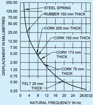
FIG. 1 RELATION BETWEEN STATIC DEFLECTION AND NATURAL FREQUENCY
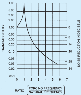
FIG. 2 TRANSMISSIBILITY AND EQUIVALENT NOISE REDUCTION FOR DIFFERENT RATIOS OF FORCING AND NATURAL FREQUENCIES
Materials for isolators and their position are given below:
a) Material for Isolators — Vibration isolators are usually made of resilient materials like steel in the form of springs, rubber cork and felt.
Because of the large range of deflections obtainable in coil springs, they may isolate vibrations over a large spectrum of low frequencies. Metal springs transmit high frequency (from about two hundred to several thousand c/s) very readily. Transmission of these frequencies can be reduced by eliminating direct contact between the spring and the supporting structure. Rubber or felt pads may be inserted between the ends of the spring and the surfaces to which it is fastened.
Rubber in the form of pads may be used to isolate very effectively engines, motors, etc. It may be used in compression or in shear. Some rubber mountings use rubber-in-shear as the primary elastic elements and rubber-in-compression as a secondary element which furnishes snubbing action if the mounting is subjected to an overload.
Felt or cork or both may be used as resilient mats or pads under machine bases. The load per unit area shall be
chosen to produce enough deflection for the isolation required; and shall be such that at this deflection, it is not loaded beyond its elastic limit.
b) Position of Isolator — The normal position of the isolators is between the machine and its foundation. However, if the forcing frequency of the machine is low (less than 10 H ) and vibration isolators with the requisite deflection for this location are not available, the machine may be bolted directly to an independent heavy inertia concrete base and the available vibration isolators used below the concrete base.
Large press and drop hammers which create serious impact vibration in heavy machine shops may be mounted rigidly on very massive blocks of concrete having weights several times greater than the weights of the supported machines. The inertia blocks may, in turn, be isolated from the building structure by large wooden blocks and with thick pads of cork.
In critical installations (see Note), attempt should be made to locate the resilient mounts in a plane which contains the centre of gravity of the mounted assembly. It is also preferable to locate the mounts laterally as far away as possible from the centre of the machine.
NOTE — Critical installations are those installations where transmission of vibration from these installations will seriously hamper the normal working.
Rigid mechanical ties between vibrating machine and building structure, shortcircuit or reduce the effectiveness of isolators. Loose and flexible connections should be inserted in all pipes and conduits leading from the vibrating machine. Where flexible connections are impracticable, bends should be inserted into the pipes or the pipes themselves should be supported on vibration mounts for a considerable distance from the source.
Flexibility of foundation — The effect of flexibility of the foundation on the isolator transmissibility shall be considered in the selection of practical vibration isolating mountings. The simplified vibration isolation theory assumes a completely rigid foundation. However, in practice, this can never be
achieved. The foundation is never actually completely rigid. Generally, the relatively low stiffness of the isolation system permits the assumption of the foundation to be rigid. However, if the stiffness of the isolator is allowed to become comparable to the foundation stiffness (or greater), the deflection of the isolator will become smaller and the foundation will also deflect with increased transmissibility and decreased isolator efficiency. In a dynamic sense, supporting foundation or floors should have natural frequency as high and be as stiff as possible compared to the system being isolated. Good design practice requires that the isolators should be designed assuming a rigid foundation with the stipulation that the selected machine isolation system frequency should be well below the foundation frequency. This point should specially be kept in mind when installing machines at upper levels in buildings because supported slabs generally have lower natural frequencies (low stiffness) than slabs on grade in basement or ground floor locations.
Air-borne noise generated by a machine may be reduced by placing the machine in an enclosure or behind a barrier. The enclosure may be in the form of close-fitting acoustic box around the machine such that the operator performs his normal work outside the box and thus is not subjected to the high noise levels of the machine. The enclosure may be made of sheet metal lined inside with an acoustical material.
Where size of the machine, working area and the operation do not permit close-fitting enclosures, the machine may be housed in a room of its own. The inside of the enclosure should be lined with soundabsorbing materials to reduce the noise level of the contained sound. The bounding walls of the enclosures shall also have adequate transmission loss to provide desired insertion loss.
A partial reduction of noise in certain directions may be obtained by ‘barriers’ or partial enclosures or partial height walls. Two-sided or three-sided barrier, with or without a top and invariably covered on the machine side with acoustic absorption material should face a wall covered with sound-absorbing material. If the top
of the enclosure is open, the reduction may be increased by placing sound-absorbing material on the ceiling overhead.
In order to reduce the general reverberant noise level in machine shops, acoustical material may be placed on the ceiling and side walls. With this treatment 3 to 6 dB reduction of middle and high frequency noise may be achieved. While the noise level at the source, affecting the operator, may not be reduced materially, the treatment would bring down the general noise level away from the source in reverberant field.
For efficient noise reduction ‘functional sound absorbers’ may be clustered as near the machines as possible. These units may be suspended and distributed in any pattern to obtain lower noise levels within the machine shop. Compared on the basis of equal total exposed surface areas, functional sound absorbers have higher noise reduction coefficients (NRC) than conventional acoustical materials placed directly on ceilings and walls.
As the individual sound pressure levels are logarithms of the mean square sound pressures, they cannot simply be added arithmetically. Figure 3 shows a graphical method for adding the sound pressure levels from two independent sources to obtain the combined sound pressure level at a particular place. This graph may also be used for multiple sources by combining sources two at a time to produce virtual sources that can then be combined. The most accurate approach is to start with the lowest levels and work towards the highest.
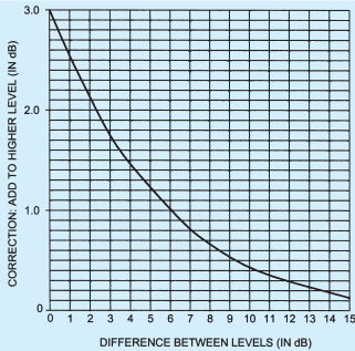
FIG. 3 THE ADDITION OF TWO NOISE LEVELS
The graph should be used with caution where the noise sources are not independent. For example, the sound pressure level from two large transformers fed with currents in phase will be very sensitive to the receiving position. This is because the effect of the constructive and destructive interference of the sounds from the two sources is very dependent on position.
When measuring noise from a source, the true noise level of the source alone will be less than that shown by the meter if the level of extraneous noise is less than about 10 dB below the total noise level. An estimate of the true source level can be obtained from Fig. 4.
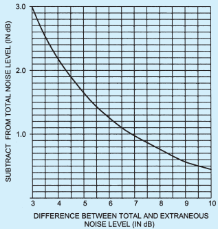
FIG. 4 SUBTRACTION OF NOISE LEVELS
Figure 5 how to calculate the overall sound insulation of a composite partition consisting of two parts having different sound — insulating properties, for example a window in a wall. It may also be used to give an indication of the effect of gaps or holes in a partition by assigning a sound insulation value of 0 dB to the aperture.
The equivalent A-weighted level is often required when data on a noise source is available as a set of octave band or one-third octave band levels. The conversion can be done manually, using the standard A-weighting values (Table 10) and the graph for combining levels (Fig. 3). For all but the simplest situations it is more convenient to use a computer spreadsheet to do the conversion.
| Third Octave A-Weighting Third Octave A-Weighting Band Center Band Centre Frequency Frequency Hz dB Hz dB(1) (2) (3) (4) |
|---|
| 10 -70.4 500 -3.212.5 -63.4 630 -1.916 -56.7 800 -0.820 -50.5 1 000 025 -44.7 1 250 0.631.5 -39.4 1 600 1.040 -34.6 2 000 1.250 -30.2 2 500 1.363 -26.2 3 150 1.280 -22.5 4 000 1.0100 -19.1 5 000 0.6125 -16.1 6 300 -0.1160 -13.4 8 000 -1.1200 -10.9 10 000 -2.5250 -8.6 12 500 -4.3315 -6.6 16 000 -6.6400 -4.8 20 000 9.3 |
An estimate of the reverberation time (T) of a room can be obtained from the Sabine formula:
where
V = is the volume of the room in cubic metres (m3);
A i = is the equivalent sound absorbing area in the room in square metres (m2).
The A i are the absorbing areas of each surface, or other permanent fixture in the room. Each A i is determined by multiplying the area of that surface in square
RATIO OF AREAS (LOWER INSULATION: HIGHER INSULATION)
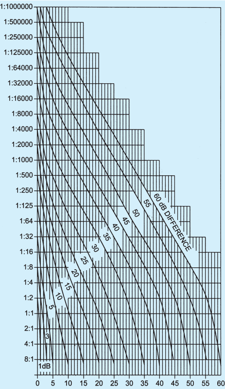
LOSS OF INSULATION: DEDUCT FROM HIGHER INSULATION (IN dB)
FIG. 5 SOUND INSULATION OF NON-UNIFORM PARTITIONS
metres ( m 2 ) by its absorption coefficient α s i * The surface of each significant fixture or feature of the room should be considered as well as the walls, ceiling and floor.
The total absorption is obtained by summing the
individual A i values. As the values of α s i are frequency dependent, this calculation should be repeated for each octave band of interest.
An allowance should also be made for people and furnishings in the room.
(Clauses 2.24, 2.38, 2.41, 2.50, 2.51, 2.52 and 2.53)
Specification of Sound Insulation
Sound insulating elements work mainly by reflecting sound energy back into the source room, not by absorbing it. The methods of measurement and the terms used are described in B-2 to B-4.
As per the standard tests, the insulation between a pair of rooms is measured either in third octave bands having centre frequencies which cover at least the range 100 Hz to 3 150 Hz, or in octave bands which cover at least the range 125 to 2 000 Hz. The noise is produced by a loudspeaker in one of the rooms (called the source room) and at each frequency the average noise levels are measured in the source room ( L S ) and in the adjacent receiving room ( L R ) . The difference between these two levels (D) is a measure of the sound insulation between the rooms regardless of the transmission path(s) the sound energy followed to travel between the rooms. The equation is as follows:
D = L S - L R
The actual level in the receiving room depends on:
a) the sound insulation of the separating wall or floor,
b) the area of the separating wall or floor;
c) the volume of the receiving room;
d) the amount of flanking transmission (that is the importance of transmission paths other than the separating wall or floor); and
e) the amount of absorbing material (for example furniture) in the receiving room.
For field measurements, apart from the amount of absorption, these factors are a property of the building and should be taken into account by the measurement procedure. As the amount of absorbing material (for example soft furniture) in the room at the time of measurement is arbitrary, it should be allowed for separately. This is achieved by measuring the reverberation time (T ) of the room in seconds (s), which is a measure of how long it takes a sound to die away after the source has been switched off. As the sound energy is dissipated as heat in the absorbing material (T), it is related to the total amount of absorption in the room. The receiving room level may then be corrected to the level it would be if the room had a standard reverberation time ( T 0 ) which is typical of furnished rooms, and is taken to be 0.5 s. The
corrected level difference is known as the standardized level difference, which has the symbol D n T and is calculated using the following equation:
For laboratory measurements, the insulation of the separating wall or floor being tested is required in a way which is independent of the actual measuring laboratory. For this reason, laboratories are designed to have minimal flanking transmission and a different correction is applied to account for the other factors. This correction is 10 log 1 0 ( S / A )
where
S = is the common area of the separating wall or floor in square metres (m2); and
A = is the equivalent absorption area in the receiving room in square metres (m2).
The laboratory corrected level difference at each frequency is known as the sound reduction index, which has the symbol R and is calculated using the following equation:
If the test wall or floor is mounted in a realistic way in the laboratory and flanking transmission will be low in the field, the sound reduction index may be used to predict its performance in the field. The relation between D n T and R is D nT = R - 10 10 (3S/V)
where
31
S = is the area of the separating wall or floor in the field in square metres (m2); and
V = is the volume of the receiving room in the field in cubic metres (m3).
This equation shows that if the source and receiving rooms have different volumes, D n T will depend on which is used as the source room; using the larger room as the source room will give lower value.
The procedure to measure the impact insulation of floors is rather different. Instead of a loudspeaker, a machine containing five small hammers is placed on the floor. While the hammers strike the floor at a rate of 10 blows a second, the resulting noise level ( L i ) is measured in the receiving room below at each of the same frequency bands used for airborne insulation. In the field, the receiving room levels are again
corrected' to a standard reverberation time (T_0) of 0.5 s to give the standardized impact sound pressure level, L nT* which is calculated as follows:
In the laboratory, the noise level depends mainly on the characteristics of the floor being tested and the amount of absorption (A m ²) in the laboratory. It is therefore appropriate to correct the noise level to a standard area of absorption. The area used is 10 m ². The resulting normalized impact sound pressure level is given the symbol L n and calculated as follows:
Measurements of insulation against both air-borne and impact sound yield values in a number of frequency bands. To make this information more manageable, rating methods such as those in accordance with [8-4(1)]are used to reduce the frequency band values to single figure ratings. These single figure ratings should be good predictors of subjective assessments of insulation. However, this is not always the case and it is prudent to examine the full measurement data in critical situations. The impact insulation measured on
a floor with a carpet is likely to be overestimated by this method.
The more common indices used to describe sound insulation are summarized in Table 11.
| Air-borne (A) Impact (I)(1) | Lab (L) Field (F)(2) | Measured Values | Single Number Quantity | ||
| Name(3) | Symbol(4) | Name(5) | Symbol(6) | ||
| A | F | Standardized level difference | DnT | Weighted standardized level difference | DnT,w |
| A | L | Sound reduction index | R | Weighted sound reduction index | Rw |
| I | F | Standardized impact sound pressure level | L′ nT | Weighted standardized impact sound pressure level | L′ nT,w |
| I | L | Normalized impact sound pressure level | L′ n | Weighted normalized impact sound pressure level | L′ n,w |
12.2.1 In large libraries, museums and art galleries
echoes from lofty, large domed or concave ceilings are often a nuisance. Small noises such as footsteps, coughs, chair scraping and closing of books are reinforced by reverberation, and concave surfaces even when treated with a sound absorbent may focus these noises. Treated flat ceilings, if not too high, obviate these troubles. Books on shelves in libraries constitute a valuable wall absorbent.
12.2.2 Floor finishes are important. The impact noise of footsteps on marble, terrazzo or wood block flooring, and especially on hardwood strip and batten flooring, can be disturbing both within the room in which the noise is generated and the rooms below. On solid floors, resilient floor finishes, such as rubber, cork and linoleum on an underlay, are highly desirable. In the children’s sections of libraries and museums they are essential. In existing buildings, rubber linoleum or vinyl asbestos tiles laid over the floor in the traffic areas are often a solution to the problem.
12.2.3 Reference libraries in universities, research establishments, office buildings and science buildings having machines and testing benches, should be planned in a quiet part of the building. Walls enclosing the library should normally have a sound reduction index, R w of not less than 50 dB (for example 230 mm brick) and baffle lobbies should be planned between the library and halls and corridors. Walls facing on to corridors or other noisy areas should not have fanlights unless they are double glazed and non-operable.
The sources of noise that have to be considered in concert halls, opera house, theatres and similar auditorium buildings are as follows:
a) Outdoor noise entering through walls, roofs, doors, windows or ventilation openings;
b) Noise from any other hall in the same building, especially if let out separately for revenue;
c) Noise from foyers, service rooms and other ancillary rooms, particularly rehearsal rooms; and
d) Noise from air conditioning plant, etc, and the cross-transmission of other internal noises via ventilating duct system.
12.3.1 Because of greatly increased outdoor noise, all auditorium buildings now need more care in siting than formerly. For listening to speech or music, a very low background noise level is desirable; in concert halls especially the quietest possible conditions should be provided because the pauses and moments of silence which are an essential element of music cannot
otherwise be given full value. Therefore, sites at cross-roads or close to steel railway bridges, religious places or near churches where bell ringing is practiced, should be avoided unless very high standards of structural sound insulation are contemplated. Sites adjoining underground railways may also prove unsatisfactory at basement levels owing to low-pitched noise or rumble transmitted through the ground; special isolation measure need to be adopted for isolating large buildings from ground vibration of this sort.
12.3.2 Whenever possible, for concert halls and theatres on city sites a noise survey of the site should be made; a suitable sound reduction value for the structure of the building can then be chosen so as to keep down to certain maximum noise levels within the auditorium. The maximum octave-band sound pressure levels (SPL) recommended are given in Table 8.
| Type of Auditorium | Centre Frequency (Hz) | |||||||
| 63 | 125 | 250 | 500 | 1 000 | 2 000 | 4 000 | 8 000 | |
| Concert Halls [dB(A)-25] | 51 | 39 | 31 | 24 | 20 | 17 | 14 | 13 |
| Drama Theatres and Cinemas [dB(A)-30] | 55 | 44 | 35 | 29 | 25 | 22 | 20 | 18 |
12.3.3 The minimum standard of sound reduction index, R w likely to be required for the envelope of an auditorium in a city to protect it against external noise is of the order of 65 dB for a concert hall or 55-60 dB for a theatre. This reduction should be provided on all sides, but it would be reasonable to make the R w for the roof 5 to 10 dB less provided the building is not unduly exposed to noise from aircraft in flight. Surrounding the auditorium with ancillary rooms and foyers is an obvious and invaluable planning method of obtaining the required insulation against outdoor noise.
12.3.4 Ventilation intakes and returns are vulnerable features in the defence against external noise. They should be positioned so as to avoid exposure to noise, and in addition sufficient length of both inlet and outlet ducts should be provided with carefully designed silencers. The ventilation system should also be designed to avoid transmitting or adding to internal noise.
12.3.5 The most serious internal noise problem arises when there are two halls meant for separate use in the same building, especially if one of them is a concert hall. The latter is a very loud potential source of noise
and requires a high standard of protection against extraneous noise. In these circumstances it is doubtful whether a ‘single’ wall can be adequate for insulating the two halls unless it is designed with a wide unbridged cavity. Separation by planning is preferable.
12.3.6 Other sources of internal noise are rehearsal rooms, scenery bays and workshops, stages of other halls where rehearsals or erection of stage sets might be in progress and foyers and bars where loud conversation might occur. The insulation of the internal walls should be adequate to protect the auditorium from these noise sources and the insulation should not be by-passed by openings, doorways, etc. The general noise due to banging of doors also needs to be taken care of; soft sealing materials should be provided for all doors to ensure quiet closing.
12.3.7 For detailed acoustical design of auditoria and conference halls reference may be made to good practice [8-4(3)].
The main objective of the design should be to control noise from adjacent screens, the projection area, the foyer, and outside the cinema. The first of these, controlling noise from adjacent screens, is likely to be the most difficult with modern digital sound systems. As most cinemas are air conditioned, there will be some noise from services. To ensure reasonable listening conditions, this should be limited to 30 dBA. This will provide some masking of the noise from adjacent screens, but a high performance partition will still be essential. Masonry or lightweight construction may be used, and a typical performance specification for a lightweight wall separating two screens is given
in Table 9. Cinema design, however, normally requires specialist acoustic advice.
| Octave Band Sound Reduction Index Hz R, dB |
|---|
| 63 38125 44250 50500 611 000 572 000 584 000 578 000 55 |
Special Problems Requiring Expert Advice
Certain design problems require reliable advice of a kind which is not easy to find in published material. The advice of an expert should be sought for these kinds of problems, some examples of which are given in E-2 to E-9.
The design of rooms in which acoustic measurements are carried out, such as reverberation chambers, freefield anechoic rooms and audiometric test rooms, usually requires the advice of an expert.
The design of theatres, opera houses, concert halls
and similar performing spaces usually requires expertise in room acoustics and noise control. The intrusion of quite low levels of noise may seriously interfere with the enjoyment of the performance and distract the performers. The requirements for low noise levels often mean that more room has to be allocated for low velocity ventilation ductwork and the impact on the design of the ventilation system is often substantial.
Broadcasting and recording studios have requirements similar to those of performing spaces. For some infrequent intrusive noises, the requirements are sometimes relaxed on the grounds that a re-take of a
recording can be done, but this can result in higher operating costs.
As there are many variables affecting the level of aircraft noise heard on the ground, expert advice is almost always required. Contours of daytime L A e q , T levels are available from most major airports. Where measurements of façade insulation are necessary a standard test method may be referred.
Projects involving ground-borne noise from underground trains usually require expert advice.
Projects involving low-frequency noise usually require expert advice as accurate measurement is difficult and there is a shortage of reliable data below 100 Hz.
Active noise control is the reduction of noise by cancellation with a similar noise (anti-noise) generated by electro-acoustic means. The technique is still under development, but commercial systems are available which successfully reduce low frequency noise from mechanical ventilation systems.
Noise surveys are carried out for a variety of reasons, for example:
a) before construction, to establish the existing noise climate at the site of a proposed development where reliable prediction is impracticable, as an aid to the design of the building envelope, either to protect against external noise or contain internally produced noise;
b) during construction, to monitor noise from building activity, either to assess the likely nuisance to the local community or the risk of hearing damage to the work force;
c) at the end of a building contract to check the insulation of the building envelope, or the noise levels produced by the services;
d) as part of a planning requirement; and
e) to provide objective evidence to support or defend a legal action.
The expense of carrying out a comprehensive noise survey of any kind is likely to be high, so the costeffectiveness of a full or partial survey should be weighed against alternatives such as prediction. A survey will generally be more accurate and can take account of factors such as prevailing wind conditions.
C-1 Noise rating (NR) is a graphical method for assigning a single number rating to a noise spectrum. It can be used to specify the maximum acceptable level in each octave band of a frequency spectrum, or to assess the acceptability of a noise spectrum for a particular application. The method was originally proposed for use in assessing environmental noise, but was later also found suitable for describing noise from mechanical ventilation systems in buildings. To make a rating, the noise spectrum is superposed on a family of NR contours; the NR of the spectrum corresponds to the value of the first NR contour that is entirely above the spectrum. The data for drawing NR contours (from NR 0 to NR 75) is given in Table 12 for the frequency range 31.5 Hz to 8 kHz.
C-2 For computational methods the curves are defined by the equation:
L = a + b N
where
L = is the octave band sound pressure level corresponding to NR level N; and
a and b = are constants for each frequency band, as given in Table 13.
NOTE — NR values can not be converted directly to dBA values but the following approximate relationship applies:
NR = dBA-6
C-3 Although the NR system is currently the preferred method for rating noise from mechanical ventilation system, other methods which are more sensitive to noise at low frequencies are available, but they are not yet widely accepted. Low frequency noise may be disturbing or fatiguing to occupants, but may not have much effect on the dBA or NR value.
| Noise Rating | Octave Band Centre Frequency, Hz Sound Pressure Levels dBre 20μPa | ||||||||
| 31.5(2) | 63(3) | 125(4) | 250(5) | 500(6) | 1 000(7) | 2 000(8) | 4 000(9) | 8 000(10) | |
| NR75 | 106 | 95 | 87 | 82 | 78 | 75 | 73 | 71 | 69 |
| NR70 | 103 | 91 | 83 | 77 | 73 | 70 | 68 | 66 | 64 |
| NR65 | 100 | 87 | 79 | 72 | 68 | 65 | 62 | 61 | 59 |
| NR60 | 96 | 83 | 74 | 68 | 63 | 60 | 57 | 55 | 54 |
| NR55 | 93 | 79 | 70 | 63 | 58 | 55 | 52 | 50 | 49 |
| NR50 | 89 | 75 | 66 | 59 | 53 | 50 | 47 | 45 | 43 |
| NR45 | 86 | 71 | 61 | 54 | 48 | 45 | 42 | 40 | 38 |
| NR40 | 83 | 67 | 57 | 49 | 44 | 40 | 37 | 35 | 33 |
| NR35 | 79 | 63 | 52 | 45 | 39 | 35 | 32 | 30 | 28 |
| NR30 | 76 | 59 | 48 | 40 | 34 | 30 | 27 | 25 | 23 |
| NR25 | 72 | 55 | 44 | 35 | 29 | 25 | 22 | 20 | 18 |
| NR20 | 69 | 51 | 39 | 31 | 24 | 20 | 17 | 14 | 13 |
| NR15 | 66 | 47 | 35 | 26 | 19 | 15 | 12 | 9 | 7 |
| NR10 | 62 | 43 | 31 | 21 | 15 | 10 | 7 | 4 | 2 |
| NR5 | 59 | 39 | 26 | 17 | 10 | 5 | 2 | -1 | -3 |
| NR0 | 55 | 35 | 22 | 12 | 5 | 0 | -4 | -6 | -8 |
| Octave Band Centre a b Frequency Hz(1) (2) (3) |
|---|
| 31.5 55.4 0.68163 35.4 0.790125 22.0 0.870250 12.0 0.930500 4.2 0.9801 000 0.0 1.0002 000 -3.5 1.0154 000 -6.1 1.0258 000 -8.0 1.030 |
D-1 Government notifications are issued from timeto-time on the allowable ambient noise levels in general and specifically in different zones of various metropolitan cities of India.
D-2 Noise regulations and notifications are also issued from time-to-time specifying the maximum permissible sound levels from equipments commonly used in and
around the residential areas and around sensitive buildings, specifically with regard to noise levels from electricity generating sets, construction equipment and HVAC utility equipment installed outdoors.
D-3 These regulations should be referred to by the designer for the design of measures for control of external noise.
In a test house or laboratory, where research workers and scientists are engaged in performing sophisticated experiments, the external noise is mostly contributed by noise emitting buildings (workshops, machine rooms), airports, railway stations and general traffic noises. The outdoor sources of noise in a college laboratory include noises produced in a playground as well.
The following sources mainly contribute to indoor noises in research institutions/college laboratories:
a) Workshops, machine rooms, cafeteria, etc;
b) Air-conditioning and exhaust fans;
c) Noise produced within the test house or laboratory while performing experiments; and
d) Typing or other machine noises, telephone service, lift, sanitary services, etc.
While planning for a laboratory or test house, care
should be taken in the design that no noise emitting installations should exist in its neighbourhood. However, where outdoor noises exist, such as from local factory, heavy traffic airports, railway lines, sport grounds or busy markets, buildings should be kept as far away as possible from the source of noise.
11.2.1.1 The window and door openings towards the noise sources should be minimum. Minimum amount of glazing should be placed on walls directly facing the noise sources.
11.2.2.1 Noisy places should be kept separate from the quiet ones. The location of laboratories or test houses should be so chosen that it is cut off from the noisy zones. Where there are offices attached to a laboratory, provision should be made to treat the offices and to use acoustical partitions, to achieve a sound isolation D w of at least 35 dB.
11.2.2.2 In a laboratory, mostly hard reflecting surfaces and bare furnishings are found, which produce very reverberant conditions. The noise condition still deteriorates when noise producing instruments are switched on or a heavy object is dropped on the floor. Under these conditions, sound absorbing treatment of the space is very essential. Sound absorbing ceilings are recommended to deaden such noises. Rubber buffers may also be fitted to the legs of furniture.
11.2.2.3 In large span laboratories or test houses where scientists and researchers are engaged in work and/or simultaneously busy in calculations or desk work requiring high degree of mental concentration, use of sound absorbing screens is recommended.
11.2.2.4 Noise reduction between the test house or laboratory and corridors or general circulation space should be well kept in mind and due care should be taken of the type of doors and the manner of their fittings etc. Transmission of noise through service ducts, pipes, lifts and staircases should also be guarded.
Telephones should preferably be placed in a separate small enclosure or acoustically efficient telephone booth.
11.2.2.5 To isolate a laboratory or a test house from structure borne noises originating from upper floor, sandwich type floor construction is recommended.
11.2.2.6 Wherever the provision of double glazed windows is necessary to reduce the heat losses, care should be taken to provide sealed double windows rather than double glazing in a single window.
NOTE — Double glazed windows for sound insulation should have a minimum gap of 100 mm between the two glasses.
Air-borne and Impact Sound Insulation
Air-borne sound refers to sources which produce sound by directly setting the air around them into vibration. Impact sound refers to sources which produce sound by impulsive mechanical excitation of part of a building (for example by footsteps, electric light switches, slamming doors). Many sources of impact sound also produce significant levels of airborne sound. The term structure-borne sound has no very precise meaning as the structure can be excited by both airborne and impact sources; it is often used to refer to sound that travels for long distances via the structure, especially in connection with vibrating machinery linked directly to the structure.
A double leaf wall can perform better than a single leaf wall of similar mass because the sound has to pass through two barriers. If the two leaves are not connected to each other, the insulation values of the two leaves may be added together. However, in practice the leaves are often connected by ties or studs, and the full insulation cannot be achieved. Even where the two leaves are isolated from each other, the full benefit can only be obtained above a certain frequency that depends on the cavity width. This is because the air in the cavity behaves like a spring connecting the leaves together, and causes a resonance at the mass-springmass frequency. Below this frequency, the two leaves behave more like an equivalent single leaf.
Making the cavity width wide can reduce the massspring-mass frequency, as in the case of sound insulating secondary glazing. The mass-spring-mass frequency ( F 0 ) may be estimated from the following equation:
where
The coincidence effect occurs when the wavelength of the wave impressed on the panel by the incident sound wave is close to the wavelength of free bending waves in the panel. The effect of coincidence is to lower the sound insulation of a construction by as much as 10 dB below the level expected from its mass per unit area over a limited frequency range. The coincidence effect can be pronounced with thin lightweight partitions, resulting in loss of insulation at middle and high frequencies. Reducting the stiffness without a corresponding reduction of mass can raise the critical frequency above 3 150 Hz, and so improve the insulation over the important 100 Hz
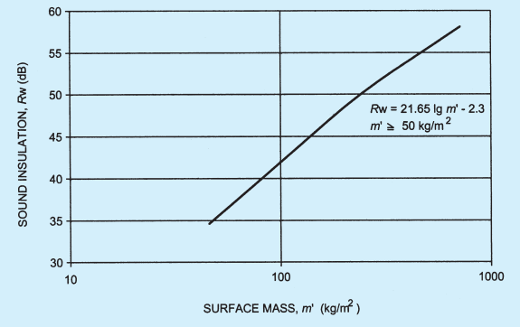
FIG. 8 MASS LAW CURVE
to 3 150 Hz range. An increase of stiffness will have the reverse effect.
It is possible to design lightweight stud partitions so that they perform to their maximum effect in the speech frequency region between 250 Hz and 2 000 Hz, that is between the mass-spring-mass and coincidence regions respectively.
The worst coincidence dips occur in materials such as plate glass and rigid metal sheets. Heavily damped materials such as lead sheets are least affected.
An approximate empirical relationship has been established between sound insulation and mass for single leaf constructions as shown in Fig. 8. This so called ‘mass law’ gives a useful first approximation to the behaviour of a single sheet or plate. In practice, the sound insulation predicted by the mass law may not be attained because of factors such as the coincidence effect, which is outlined in F-3.4. Results for specific materials vary around the value given by the mass law relationship, and so measured data should be used when available. Table 14 gives a lists of materials and indicates the sound insulation of a single, imperforate sheet when fixed to a suitable wood or metal framework. These values are useful, for example when assessing existing structures.
| Material Surface Typical Weighted Mass Sound Reduction Index, R<sub>w</sub> kg/m<sup>2</sup> dB(1) (2) (3) |
|---|
| 3 mm glass sheet 7.0 26 12.5 mm plasterboard 10.5 31 18 mm wood particle board 8.0 27 19 mm plywood 3.0 24 16 mm plywood 4.5 24 1 mm steel sheet 11.0 29 6 mm hardboard 5.0 25 12 mm wood fibre insulation 4.0 24 board 13 mm mineral fibre board 4.0 24 50 mm wood-wool screeded 35.0 33 one side |
Figure 6 shows diagrammatically a pair of rooms in a house where the construction consists of solid walls, etc bonded together. Sound travelling from room 1 to
room 2 may travel via the direct path a-a and by the many indirect, or flanking, paths shown. The term flanking transmission is usually used to mean transmission paths involving the structure, while the term indirect transmission includes flanking paths and airborne paths through gaps and ducts, etc. The indirect paths may limit the sound insulation attainable no matter how much the direct sound is reduced by the separating wall or floor. The indirect transmission can be reduced by measures such as the following:
a) Increasing the mass of the flanking walls;
b) Increasing the mass of the partition and bonding it to the flanking walls;
c) Introducing discontinuities in the indirect paths;
d) Erecting independent wall linings adjacent to the flanking walls to prevent energy entering the flanking construction; and
e) Sealing any air gaps and paths through ducts.
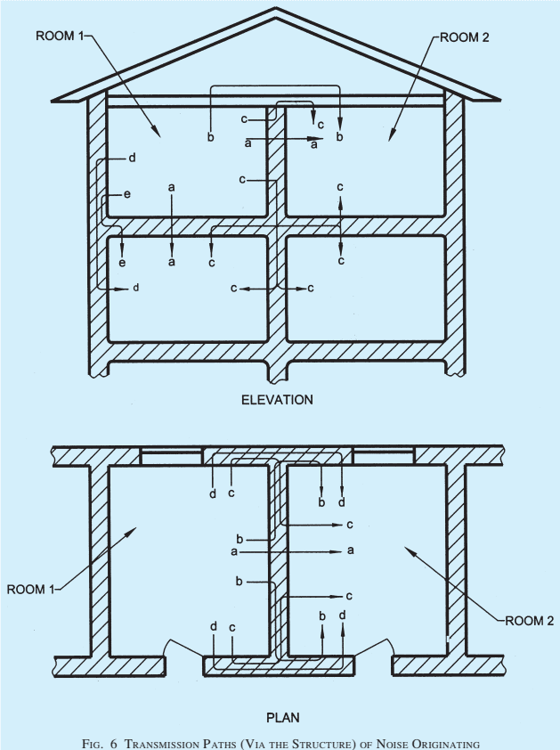
FIG. 6 TRANSMISSION PATHS (VIA THE STRUCTURE) OF NOISE ORIGINATING IN ROOM 1 (DIAGRAMMATIC)
Figure 7 shows a number of indirect paths that have been found in offices.
It is important to remember that standard test laboratories are designed to minimize transmission by all paths other than the direct path. This makes it difficult to relate the results of laboratory
measurements to those likely to be obtained in the field.
F-3 Air-borne Sound Insulation
The sound insulation of structural elements such as
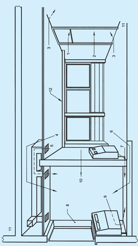
FIG.7INDIRECT SOUND LEAKAGE PATHS
walls and floors always varies with frequency, the insulation rising in general as the frequency rises.
Results from field measurements are usually expressed in terms of the weighted standardized level difference, while laboratory measurements are usually expressed in terms of the sound reduction index. In the absence of significant flanking transmission, the numerical difference between the weighted standardized level difference and the sound reduction index of a wall or floor is usually small for furnished rooms in dwellings, and so either quantity may be used in considering principles; for this purpose it is, therefore, convenient to use the general term insulation.
Table 15 and Table 16 give examples of common types of wall and floor construction with sound insulation in the ranges shown. The insulation indices are for field measurements accessed in accordance with [8-4(5)]. The insulation values given are necessarily approximate since examples of nominally identical constructions may show variations of several decibels. All the figures represent values expected in the field, that is in actual buildings. Many are based directly on field measurements, though other (in the absence of representative field measurements) have been assessed from laboratory data, with an allowance for typical flanking conditions in normal buildings. Variation in the amount of indirect transmission may affect significantly the insulation between two rooms separated by a given barrier. For example, the sound insulation of some types of floor may be reduced by indirect transmission along the walls supporting them, particularly if these walls are of lightweight masonry and carried past the floor.
| (Clause F-4) | |
|---|---|
| Sound | Type of Wall or Partition |
| Insulation | |
| D<sub>nT</sub>,w | |
| dB | |
| (1) | (2) |
| 26 to 33 | a) 1 mm steel sheet panels fixed to steel frame members to form demountable partition units 50 mm overall thickness. Mineral wool cavity insulation. b) Plywood or wood fibre board 12 mm thick nailed both sides of 50 mm × 50 mm timber framing members spaced at 400 mm centres. c) Paper faced strawboard or wood wool 50 mm thick panels plastered both sides. d) Chipboard hollow panels 50 mm thick tongued and grooved edges, hardboard faced. Joints covered with wood trim. |
| 33 to 37 | a) Lightweight masonry blockwork. Plaster or drylining on at least one side. Overall mass per unit area not less than 50 kg/m<sup>2</sup>. b) Laminated plasterboard at least 50 mm thick fixed to timber perimeter framing, any suitable finish. Approximate mass per unit area 35 kg/m<sup>2</sup>. |
| Table 15 —Continued | Table 15 —Concluded | ||
| (1) | (2) | (1) | (2) |
| 37 to 43 | c) Timber stud partitions any size timbers greater than 50 mm × 50 mm, 400 mm centers, cross noggins, 9.5 mm plasterboard lining on both sides, any suitable finish.d) Metal stud partition, 50 mm studs 600 mm centres, clad both sides with 12.5 mm plasterboard, joints filled and perimeters sealed. Approximate mass per unit area 18 kg/m2.e) 50 mm lightweight masonry blockwork, plastered both sides to 12 mm thickness or drylined with 9.5 mm plasterboard.a) Lightweight masonry blockwork, plaster or dry lining on at least one side. Overall mass per unit area not less than 75 kg/m2.b) Either 75 mm or 100 mm × 50 mm timber studs spaced 600 mm apart, 50 mm mineral fibre quilt in stud cavity. Frame lined on both sides with one layer 12.5 mm plasterboard. Approximate mass per unit area 19 kg/m2.a) Masonry wall, joints well filled. Either plaster or dry lining on both sides. Overall mass per unit area not less than 150 kg/m2.b) 100 mm metal stud partition, ‘C’ section studs not greater than 600 mm spacing, not less than nominal 50 mm web depth. Clad on both sides with two layers of plasterboard of not less than 22 mm combined thickness. Mineral fibre quilt hung between studs. Approximate mass per unit area 35 kg/m2.c) 75 mm × 50 mm timber framing using staged studs at 300 mm spacing with 25 mm stagger forward and back. Frame clad with two layers of 12.5 mm of plasterboard on both sides. Mineral fibre quilt hung between studs. Approximate mass per unit area 36 kg/m2.d) 50 mm × 25 mm timber stud partition to form a 25 mm cavity, clad on both sides with minimum 38 mm wood wool slabs having their outer faces screeded or plastered.e) Solid autoclaved aerated concrete block 215 mm thick plaster or dry lined finish on both sides, blockwork joints well filled. Overall mass per unit area not less than 160 kg/m2. | e) Cavity lightweight aggregate block (maximum density of block 1 600 kg/m3) with 75 mm cavity and wall ties of the butterfly wire type. Dry lined finish on both sides. Joints in blockwork well filled. Overall mass per unit area not less than 300 kg/m2.1)f) Dense aggregate concrete block cavity wall with 50 mm cavity and wall ties of the butterfly wire type. Dry lined finish on both sides. Joints in blockwork well filled. Overall mass per unit area not less than 415 kg/m2.1)g) Autoclaved aerated concrete block cavity wall consisting of two leaves, 100 mm blocks not less than 75 mm apart, with wall ties of the butterfly type. Plaster or dry line finish on both sides. Joints in blockwork well filled. Overall mass per unit area not less than 150 kg/m2.1)54 to 60 a) Two separate frames of timber studs not less than 100 mm × 50 mm spaced at 600 mm maximum centres. A 50 mm mineral wool quilt in each frame between studs. Frames spaced to give a minimum 300 mm overall cavity. Each frame clad on outside with three layers of 12.5 mm plasterboard nailed to framing. Approximate mass per unit area 51 kg/m2.1)b) Two separate frames of boxed ‘C’ section galvanized nominal 150 mm steel studs 100 mm apart with a 400 mm overall cavity. 50 mm mineral wool quilt fixed to the back of one frame each frame clad on outside with three layers of 12.5 mm plasterboard by self drilling or tapping screws. Approximate mass per unit area 47 kg/m2.1)c) Solid masonry with an overall mass per unit area of not less than 700 kg/m2 fully sealed both sides.1)d) Dense aggregate concrete block solid wall 215 mm thick plaster finish to both surfaces. Overall mass per unit area not less than 415 kg/m2.1)e) Cavity lightweight aggregate block (maximum density of block 1 600 kg/m3) with 75 mm cavity and wall ties of the butterfly wire type. Plaster finish on both sides. Joints in blockwork well filled. Overall mass per unit area not less than 300 kg/m2.1)f) Dense aggregate concrete block cavity wall with 50 mm cavity and wall ties of the butterfly wire type. Plaster finish on both sides. Joints in blockwork well filled. Overall mass per unit area not less than 415 kg/m2.1)NOTES1 Construction details and workmanship are important if the levels of sound insulation indicated are to be achieved.2 Where plasterboard is specified it is assumed that the surface mass will be at least 6.5 kg/m2 for 9.5 mm thick board, at least 8.5 kg/m2 for 12.5 mm thick board, and at least 14.5 kg/m2 for 19 mm thick board. If less dense plasterboard is used, the thickness should be increased. | |
Table 16 Air-borne and Impact Sound Insulation of Floor Constructions
(Clause F-4)
| Sound Insulation dB(1) | Type of Wall or Partition(2) |
|---|---|
| D<sub>nT,w</sub> = 49 to 54a)L'<sub>nT,w</sub> = 56 to 65 | A concrete floor having mass per unit areanot less than 365 kg/m², including any screedor ceiling finish directly bonded to the floorslab; together with a floating floor or resilientfloor covering equivalent to rubber or spongerubber underlay or thick cork tile (forexample carpet and underlay or spongerubber backed vinyl flooring).b) A solid floor consisting of:1) a solid slab; or2) concrete beams and infilling blocks; or3) hollow concrete planks; together with afloating floor. A ceiling finish is requiredfor a beam and block floor. In each casethe slab should have a mass per unit areaof at least 300 kg/m² including any screedor ceiling finish directly bonded to it.Where a floating floor is laid over a floor ofbeams and hollow infill blocks or hollowbeams along the top of the structural floor, itshould be sealed and levelled before theresilient layer is put down. It is also essentialto have due regard for conduits and pipeworkwhich should be laid and covered so as toprevent any short circuit of the floor’sisolating properties.If precast units are used as a structural floor,it is essential that the joints are filled to ensurethat the sound insulation performance ismaintained.The resilient material is laid to covercompletely the structural floor and turned upagainst the surrounding wall along all edges.The resilient layer is usually of mineral fibre,or a special grade of expanded polystyrene.When the screed is laid, it is important thatnone of the mix finds its way through theresilient layer to the structural floor, as thiswill short circuit the isolation between the twodecks and significantly reduce the soundinsulation.c) A floor consisting of boarding nailed tobattens laid to float upon an isolating layerof mineral fibre capable of retaining itsresilience under imposed loading. Withbattens running along the joists, a dense fibrelayer can be used in strips. The ceiling belowto be of metal lath and plaster not less than29 mm thick, with pugging on the ceilingsuch that the combined mass per unit area of |
| Table 16 - Concluded |
|---|
| (1) (2) |
| the floor, ceiling and pugging is not less than 120 kg/m<sup>2</sup>. This construction will only give values for D<sub>nT</sub>,w <sup>of</sup> <sup>50</sup> <sup>to</sup> <sup>53</sup> <sup>dB</sup>, and a value for L´nT,w <sup>of</sup> <sup>75dB</sup>. d) A floor consisting of 18 mm tongued and grooved chipboard on 19 mm plasterboard laid on battens running parallel to the joists and supported on 25 mm thick mineral wool of about 90 kg/m<sup>3</sup> to 140 kg/ m<sup>3</sup> density; 100 mm of fibre absorbent (as used for insulation in roof spaces) laid between the joists on top of the plasterboard ceiling.<sup>1</sup>) e) A floor consisting of 18 mm tongued and grooved chipboard on 19 mm plasterboard floating on a 25 mm thick mineral wool layer of about 60 kg/m<sup>3</sup> to 80 kg/m<sup>3</sup> density; this on a 12.5 mm plywood platform; 100 mm of fibre absorbent laid between the joists on top of the plasterboard ceiling.<sup>1</sup>) D<sub>nT</sub>,w = 32 to 36 Timber joist floor consisting of 22 mm L´nT,w = 80 to 85 tongued and grooved floor boarding or equivalent fixed directly to floor joists. Ceiling of 12.5 mm plasterboard and skim with no floor covering. NOTES 1 Construction details and workmanship are important if the levels of sound insulation indicated are to be achieved. 2 Where plasterboard is specified it is assumed that the surface mass will be at least 8.5 kg/m<sup>3</sup> for 12.5 mm thick board, and at least 14.5 kg/m<sup>2</sup> for 19 mm thick board. If less dense plasterboard is used, the thickness should be increased. <sup>1</sup>) In these types of floor construction, the ceiling may be 19 mm plus 12.5 mm plasterboard. It is imperative that the resilient layer is not punctured by nails. |
In many cases, simple solid partitions give insulation values according to their mass (see F-3.3). Moreover, with partitions of this type there is usually little variation between field and laboratory test results unless the laboratory insulation exceeds 45 dB. Exceptions may occur in buildings that have not been specially designed to minimize common cavities and strongly coupled elements in lightweight panelling. The examples given are not exhaustive. Flanking structures are not listed since these can vary widely and are often dependent upon other factors such as thermal insulation, which are outside the scope of this Code.
A structure that receives an impact or has a vibrating source in contact with it behaves more like an extension of the source rather than an intervening element between source and listener. For this reason, a relatively small amount of impact energy may produce a loud sound and, if the structure is continuous, the sound may travel a long distance. Control is usually obtained by inserting a resilient surface at the point of contact with the source (for example laying a carpet on a floor) or by introducing a structural discontinuity.
Floating floors, which are an example of the latter approach, are a common method of controlling impact
sound from footsteps. However, it should be noted that an effective floating floor may result in increased sound from impacts on the source side of the floor. The conventional forms of floating floor may be unsatisfactory if protection against the low-frequency content of impact noise is required (e.g. a dance floor over a restaurant).
| 43 to 50 |
| 50 to 54 | a) Two separate frames of timber studs not less than 89 mm × 38 mm, or boxed metal studwork with 50 mm minimum web depth. Studs at 600 mm maximum centres. A 25 mm mineral wool quilt suspended between frames. Frames spaced to give a minimum 200 mm overall cavity. Clad on outside of each frame with a minimum of 30 mm plasterboard layers (for example 19 mm plus 12.5 thickness). Approximate mass per unit area 54 kg/m2.1)b) Either in-situ or pre-cast concrete wall panel not less than 175 mm thick and not less than 415 kg/m2. All joints well filled.1)c) Brick wall nominal 230 mm thickness, weight (including plaster) not less than 380 kg/m2. Plaster or dry-lined finish both sides. Brick work joints well filled.1)d) ‘No fines’ concrete 225 mm thickness, weight (including plaster) not less than 415 kg/m2. Plaster or dry-lined finish both sides.1) |