This Section covers requirements and methods for lighting and ventilation of buildings.
Loading…
2.0 For the purpose of this Section, the following definitions shall apply.
2.1.1 Altitude (θ) — The angular distance of any point of celestial sphere, measured from the horizon, on the great circle passing through the body and the zenith (see Fig. 1).
2.1.2 Azimuth (φ) — The angle measured between meridians passing through the north point and the point in question (point C in Fig. 1).
CELESTIAL BODY
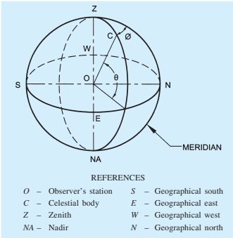
FIG. 1 ALTITUDE AND AZIMUTH OF A
5
2.1.3 Brightness Ratio or Contrast — The variations or contrast in brightness of the details of a visual task, such as white print on blackboard.
2.1.4 Candela (cd) — The SI unit of luminous intensity.
Candela = 1 lumen per steradian
2.1.5 Central Field — The area of circle round the point of fixation and its diameter, subtending an angle of about 2 ° at the eye. Objects within this area are most critically seen in both their details and colour.
2.1.6 Clear Design Sky — The distribution of luminance of such a sky is non-uniform; the horizon is brighter than the zenith, and when L z is the brightness at zenith, the brightness at an altitude (θ) in the region away from the sun, is given by the expression:
when θ lies between 1 5 ° and 9 0 ° , and L e is constant when θ lies between 0 ° and 1 5 ° ,
2.1.7 Colour Rendering Index (CRI) — Measure of the degree to which the psychophysical colour of an object illuminated by the test illuminant conforms to that of the same object illuminated by the reference illuminant, suitable allowance having been made for the state of chromatic adaptation.
2.1.8 Correlated Colour Temperature (CCT) (Unit: K) — The temperature of the Planckian radiator whose perceived colour most closely resembles that of a given stimulus at the same brightness and under specified viewing conditions.
2.1.9 Daylight Area — The superficial area on the working plane illuminated to not less than a specified daylight factor, that is, the area within the relevant contour.
2.1.10 Daylight Factor — The measure of total daylight illuminance at a point on a given plane expressed as the ratio (or percentage) which the illuminance at the point on the given plane bears to the simultaneous illuminance on a horizontal plane due to clear design sky at an exterior point open to the whole sky vault, direct sunlight being excluded.
2.1.11 Daylight Penetration — The maximum distance to which a given daylight factor contour penetrates into a room.
2.1.12 Direct Solar Illuminance — The illuminance from the sun without taking into account the light from the sky.
2.1.13 External Reflected Component (ERC) — The ratio (or percentage) of that part of the daylight illuminance at a point on a given plane which is received by direct reflection from external surfaces as compared to the simultaneous exterior illuminance on a horizontal plane from the entire hemisphere of an unobstructed clear design sky.
2.1.14 Glare — A condition of vision in which there is discomfort or a reduction in the ability to see
significant objects or both due to an unsuitable distribution or range of luminance or due to extreme contrasts in space and time.
2.1.15 Illuminance — At a point on a surface, the ratio of the luminous flux incident on an infinitesimal element of the surface containing the point under consideration to the area of the element.
NOTE — The unit of illuminance (the measurement of illumination) is lux which is 1 lumen per square metre.
2.1.16 Internal Reflected Component (IRC) — The ratio (or percentage) of that part of the daylight illuminance at a point in a given plane which is received by direct reflection or inter-reflection from the internal surfaces as compared to the simultaneous exterior illuminance on a horizontal plane due to the entire hemisphere of an unobstructed clear design sky.
2.1.17 Light Output Ratio (LOR) or Efficiency (η ) — The ratio of the luminous flux emitted from the luminaire to that emitted from the lamp(s) (nominal luminous flux). It is expressed in percent.
2.1.18 Lumen (lm) — SI unit of luminous flux. The luminous flux emitted within unit solid angle (one steradian) by a point source having a uniform intensity of one candela.
2.1.19 Luminance (At a point of a Surface in a Given Direction) (Brightness) — The quotient of the luminous intensity in the given direction of an infinitesimal element of the surface containing the point under consideration by the orthogonally projected area of the element on a plane perpendicular to the given direction. The unit is candela per square metre (cd/m2).
2.1.20 Luminous Flux (φ) — The quantity characteristic of radiant flux which expresses its capacity to produce visual sensation evaluated according to the values of relative luminous efficiency for the light adapted eye:
a) Effective luminous flux (φ ) — Total luminous flux which reaches the working plane.
b) Nominal luminous flux (φ ) — Total luminous flux of the light sources in the interior.
2.1.21 Maintenance Factor (d) — The ratio of the average illuminance on the working plane after a certain period of use of a lighting installation to the average illuminance obtained under the same conditions for a new installation.
2.1.22 Meridian — It is the great circle passing through the zenith and nadir for a given point of observation.
2.1.23 North and South Points — The point in the respective directions where the meridian cuts the horizon.
2.1.24 Orientation of Buildings — In the case of non-square buildings, orientation refers to the direction of the normal to the long axis. For example, if the length of the building is east-west, its orientation is northsouth.
2.1.25 Peripheral Field — It is the rest of the visual field which enables the observer to be aware of the spatial framework surrounding the object seen.
NOTE — A central part of the peripheral field, subtending an angle of about 30° on either side of the point of fixation, is chiefly involved in the perception of glare.
2.1.26 Reflected Glare — The variety of ill effects on visual efficiency and comfort produced by unwanted reflections in and around the task area.
2.1.27 Reflection Factor (Reflectance) — The ratio of the luminous flux reflected by a body (with or without diffusion) to the flux it receives. Some symbols used for reflection factor are:
r c = Reflection factor of ceiling.
r w = Reflection factor of parts of the wall between the working surface and the luminaires.
r f = Reflection factor of floor.
2.1.28 Reveal — The side of an opening for a window.
2.1.29 Room Index ( k r ) — An index relating to the shape of a rectangular interior, according to the formula:
where L and W are the length and width respectively of the interior, and H m is the mounting height, that is, height of the fittings above the working plane.
NOTES
1 For rooms where the length exceeds 5 times the width, L shall be taken as L = 5W.
2 If the reflection factor of the upper stretch of the walls is less than half the reflection factor of the ceiling, for indirect or for the greater part of indirect lighting, the value H m is measured between the ceiling and the working plane.
2.1.30 Sky Component (SC) — The ratio (or percentage) of that part of the daylight illuminance at a point on a given plane which is received directly from the sky as compared to the simultaneous exterior illuminance on a horizontal plane from the entire hemisphere of an unobstructed clear design sky.
2.1.31 Solar Load — The amount of heat received into a building due to solar radiation which is affected by orientation, materials of construction and reflection of external finishes and colour.
2.1.32 Utilization Factor (Coefficient of Utilizaiton) ( μ ) — The ratio of the total luminous flux which reaches the working plane (effective luminous
flux, n ) to the total luminous flux of the light sources in the interior (nominal luminous flux, φ ).
2.1.33 Visual Field — The visual field in the binocular which includes an area approximately 120° vertically and 160° horizontally centering on the point to which the eyes are directed. The line joining the point of fixation and the centre of the pupil of each eye is called its primary line of sight.
2.1.34 Working Plane — A horizontal plane at a level at which work will normally be done (see 4.1.3.3 and 4.1.3.4).
Good lighting is necessary for all buildings and has three primary aims. The first aim is to promote work and other activities carried out within the building; the second aim is to promote the safety of the people using the building; and the third aim is to create, in conjunction with the structure and decoration, a pleasing environment conducive to interest of the occupants and a sense of their well-being.
a) careful planning of the brightness and colour pattern within both the working areas and the surroundings so that attention is drawn naturally to the important areas, detail is seen quickly and accurately and the room is free from any sense of gloom or monotony (see 4.1.3);
b) using directional lighting where appropriate to assist perception of task detail and to give good modeling;
c) controlling direct and reflected glare from light sources to eliminate visual discomfort;
d) in artificial lighting installations, minimizing flicker from certain types of lamps and paying attention to the colour rendering properties of the light;
e) correlating lighting throughout the building to prevent excessive differences between adjacent areas so as to reduce the risk of accidents; and
f) installation of emergency lighting systems, where necessary.
The brightness pattern seen within an interior may be considered as composed of three main parts — the task itself, immediate background of the task and the general surroundings of walls, ceiling, floor, equipment and furnishings.
4.1.2.1 In occupations where the visual demands are small, the levels of illumination derived from a criterion of visual performance alone may be too low to satisfy the other requirements. For such situations, therefore, illuminance recommendations are based on standards of welfare, safety and amenity judged appropriate to the occupations; they are also sufficient to give these tasks brightness which ensured that the visual performance exceeds the specified minimum. Unless there are special circumstances associated with the occupation, it is recommended that the illuminance of all working areas within a building should generally be 150 lux, even though the visual demands of the occupation might be satisfied by lower values.
4.1.2.2 Where work takes place over the whole utilizable area of room, the illumination over that area should be reasonably uniform and it is recommended that the uniformity ratio (minimum illuminance divided by average illuminance levels) should be not less than 0.7 for the working area.
4.1.2.3 When the task brightness appropriate to an occupation has been determined, the brightness of the other parts of the room should be planned to give a proper emphasis to visual comfort and interest.
A general guide for the brightness relationship within the normal field of vision should be as follows:
a) For high task brightness Maximum (above 100 cd/m2)
Between the visual task 3 to 1 and the adjacent areas like table tops
Between the visual task 10 to 1 and the remote areas of the room
b) For low and medium task brightness (below 100 cd/m2): The task should be brighter than both the background and the surroundings; the lower the task brightness, the less critical is the relationship.
Table 4 gives recommended values of illuminance commensurate with the general standards of lighting
described in this section and related to many occupations and buildings; These are valid under most of the conditions whether the illumination is by daylighting, artificial lighting or a combination of the two. The great variety of visual tasks makes it impossible to list them all and those given should be regarded as representing types of task.
4.1.3.1 The different locations and tasks are grouped within the following four sections:
a) Industrial buildings and process;
b) Offices, schools and public buildings;
c) Surgeries and hospitals; and
d) Hotels, restaurants, shops and homes.
4.1.3.2 The illumination levels recommended in Table 4 are those to be maintained at all time on the task. As circumstances may be significantly different for different interiors used for the same application or for different conditions for the same kind of activity, a range of illuminances is recommended for each type of interior or activity instead of a single value of illuminance. Each range consists of three sucessive steps of the recommended scale of illuminances. For working interiors the middle value of each range represents the recommended service illuminance that would be used unless one or more of the factors mentioned below apply.
4.1.3.2.1 The higher value of the range should be used when:
a) unusually low reflectances or contrasts are present in the task;
b) errors are costly to rectify;
c) visual work is critical;
d) accuracy or higher productivity is of great importance; and
e) the visual capacity of the worker makes it ncessary.
4.1.3.2.2 The lower value of the range may be used when:
a) reflectances or contrast are unusually high;
b) speed and accuracy is not important; and
c) the task is executed only occasionally.
4.1.3.3 Where a visual task is required to be carried out throughout an interior, general illumination level to the recommended value on the working plane is necessary; where the precise height and location of the task are not known or cannot be easily specified, the recommended value is that on horizontal plane 850 mm above floor level.
NOTE — For an industrial task, working plane for the purpose of general illumination levels is that on a work place which is
generally 750 mm above the floor level. For certain purposes, such as viewing the objects of arts, the illumination levels recommended are for the vertical plane at which the art pieces are placed.
4.1.3.4 Where the task is localized, the recommended value is that for the task only; it need not, and sometimes should not, be the general level of illumination used throughout the interior. Some processes, such as industrial inspection process, call for lighting of specialized design, in which case the level of illumination is only one of the several factors to be taken into account.
Excessive contrast or abrupt and large changes in brightness produce the effect of glare. When glare is present, the efficiency of vision is reduced and small details or subtle changes in scene cannot be perceived. It may be
a) direct glare due to light sources within the field of vision,
b) reflected glare due to reflections from light sources or surfaces of excessive brightness, and
c) veiling glare where the peripheral field is comparatively very bright.
4.1.4.1 An example of glare sources in daylighting is the view of the bright sky through a window or skylight, especially when the surrounding wall or ceiling is comparatively dark or weakly illuminated. Glare can be minimized in this case either by shielding the open sky from direct sight by louvers, external hoods or deep reveals, curtains or other shading devices or by cross lighting the surroundings to a comparable level. A gradual transition of brightness from one portion to the other within the field of vision always avoids or minimizes the glare discomfort.
Most buildings are complexes of working areas and other areas, such as passages, corridors, stairways, lobbies and entrances. The lighting of all these areas should be properly correlated to give safe movement within the building at all times.
Accidents may result if people leave a well-lighted working area and pass immediately into corridors or on to stairways where the lighting is inadequate, as the time needed for adaptation to the lower level may be too long to permit obstacles or the treads of stairs to be seen sufficiently quickly. For the same reason, it is desirable that the illumination level of rooms which open off a working area should be fairly high even though the rooms may be used only occasionally.
| Sl No. | Type of Interior or Activity | Range of Service Illuminance in Lux | Quality Class of Direct Glare Limitation | Remarks |
| (1) | (2) | (3) | (4) | (5) |
| 1 | AGRICULTURE AND HORTICULTURE | |||
| 1.1 | Inspection of Farm Produce where Colour is Important | 300-500-750 | 1 | Local lighting may be appropriate |
| Other Important Tasks | 200-300-500 | 2 | Local lighting may be appropriate | |
| 1.2 | Farm Workshops | |||
| 1.2.1 | General | 50-100-150 | 3 | |
| 1.2.2 | Workbench or machine | 200-300-500 | 2 | Local or portable lighting may be appropriate |
| 1.3 | Milk Premises | 50-100-150 | 3 | |
| 1.4 | Sick Animal Pets, Calf Nurseries | 30-50-100 | 3 | |
| 1.5 | Other Firm and Horticultural Buildings | 20-30-50 | 3 | |
| 2 | COAL MINING (SURFACE BUILDINGS) | |||
| 2.1 | Coal Preparation Plant | |||
| 2.1.1 | Walkways, floors under conveyors | 30-50-100 | 3 | |
| 2.1.2 | Wagon loading, bunkers | 30-50-100 | 3 |
a) where the recommended illumination levels have to be obtained by artificial lighting only,
b) to supplement daylighting when the level of illumination falls below the recommended value, and
c) where visual task may demand a higher level of illumination.
For general lighting purposes, the recommended practice is to design for a level of illumination on the working plane on the basis of the recommended levels for visual tasks given in Table 4 by a method called ‘Lumen method’. In order to make the necessary detailed calculations concerning the type and quantity of lighting equipment necessary, advance information on the surface reflectances of walls, ceilings and floors is required. Similarly, calculations concerning the brightness ratio in the interior call for details of the interior décor and furnishing. Stepwise guidance regarding designing the interior lighting systems for a building using the ‘Lumen method’ is given in 4.3.2.1 to 4.3.2.4.
Recommended value of illumination shall be taken from Table 4, depending upon the type of work to be carried out in the location in question and the visual tasks involved.
The selection of light sources and luminaires depends on the choice of lighting system, namely, general lighting, directional lighting and localized or local lighting.
a) The luminous flux (φ) reaching the working plane depends upon the following:
lumen output of the lamps,
type of luminaire,
proportion of the room (room index) (k ),
reflectance of internal surfaces of the room,
depreciation in the lumen output of the lamps after burning their rated life, and
depreciation due to dirt collection on luminaires and room suface.
b) Coefficient of Utilization or Utilization Factor
amount of calculations, especially if these tables have to cover a wide range of lighting practices. For every luminaire, the exact light distribution has to be measured in the laboratory and their efficiencies have to be calculated and measured exactly. These measurements comprise:
i) the luminous flux radiated by the luminaires directly to the measuring surface,
ii) the luminous flux reflected and rereflected by the ceiling and the walls to the measuring surface, and
iii) the inter-reflections between the ceiling and wall which result in the measuring surface receiving additional luminous flux.
All these measurements have to be made for different reflection factors of the ceiling and the walls for all necessary room indices. These tables have also to indicate the maintenance factor to be taken for the luminous flux depreciation throughout the life of an installation due to ageing of the lamp and owing to the deposition of dirt on the lamps and luminaires and room surfaces.
White and very light colours 0.7
Light colours 0.5
Middle tints 0.3
Dark colours 0.1
For the walls, taking into account the influence of the windows without curtains, shelves, almirahs and doors with different colours, etc, should be estimated.
c) Calculation for determining the luminous flux
or, φ = E a v A µ for new condition
and φ = E a v A µ d for working condition
where
φ = Total luminous flux of the light sources installed in the room inlumens;
E = Average illumination level required on the working plane inlux;
A = Area of the working plane in m2;
= the utilization factor in new conditions; and d = maintenance factor.
In practice, it is easier to calculate straightaway the number of lamps or luminaires from:
where
N luminaires = Total number of luminaires.
This is done to achieve better uniformly distributed illumination. The location of the luminaires has an important effect on the utilization factor.
a) In general, luminaires are spaced " a " metre apart in either direction, while the distance of the end luminaire from the wall is ` / 2 a / ′ metre. The distance ° a ′ is more or less equal to the mounting height ° H m between the luminaire and the working plane. The utilization factor tables are calculated for this arrangement of luminaires.
b) For small rooms where the room index (k ) is less than 1, the distance ° a ′ should always be less than H m since otherwise luminaires cannot be properly located. In most cases of such rooms, four or two luminaires are placed for good general lighting. If, however, in such rooms only one luminaire is installed in the middle, higher utilization factors are obtained, but the uniformity of distribution is poor. For such cases, references should be made to the additional tables for k _ r = 0 . 6 to 1.25 for luminaires located centrally.
4.3.3.1 The need for general supplementary artificial lighting arises due to diminution of daylighting beyond design hours, that is, for solar altitude below 1 5 ° or when dark cloudy conditions occur.
4.3.3.2 The need may also arise for providing artificial lighting during the day in the innermost parts of the building which cannot be adequately provided with daylighting, or when the outside windows are not of adequate size or when there are unavoidable external obstructions to the incoming daylighting.
4.3.3.3 The need for supplementary lighting during the day arises, particularly when the daylighting on the working plane falls below 100 lux and the surrounding luminance drops below 19 cd/m2.
4.3.3.4 The requirement of supplementary artificial lighting increases with the decrease in daylighting availability. Therefore, conditions near sunset or sunrise or equivalent conditions due to clouds or obstructions, etc, represent the worst conditions when the supplementary lighting is most needed.
4.3.3.5 The requirement of supplementary artificial lighting when daylighting availability becomes poor may be determined from Fig. 3 for an assumed ceiling height of 3.0 m, depending upon floor area, fenestration percentage and room surface reflectance. Cool daylight fluorescent tubes are recommended with semi-direct luminaires. To ensure a good distribution of illumination, the mounting height should be between 1.5 m and 2.0 m above the work plane for a separation of 2.0 m to 3.0 m between the luminaires. Also the number of lamps should preferably be more in the rear half of the room than in the vicinity of windows. The following steps may be followed for using Fig. 3 for determining the number of fluorescent tubes required for supplementary daylighting.
a) Determine fenestration percentage of the floor area, that is,
4.4.1 A substantial portion of the energy consumed on lighting may be saved by utilization of daylight and rational design of supplementary artificial lights.
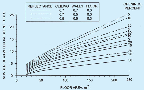
FIG. 3 SUPPLEMENTARY ARTIFICIAL LIGHTING FOR 40W FLUORESCENT TUBES
4.4.2 Daytime use of artificial lights may be minimized by proper design of windows for adequate daylight indoors. Daylighting design should be according to 4.2.
4.4.3 Fenestration expressed as percentage of floor area required for satisfactory visual performance of a few tasks for different separation to height (S/H) ratio of external obstructions such as opposite buildings may be obtained from the design nomograph (Fig. 4). The obstructions at a distance of three times their height or more (S/H > 3) from a window façade are not significant and a window facing such an obstruction may be regarded as a case of unobstructed window.
4.4.3.1 The nomograph consists of horizontal lines indicating fenestration percentage of floor area and vertical lines indicating the separation to height ratio of external obstructions such as opposite buildings. Any vertical line for separation to height ratio other than already shown in the nomograph (1.0, 2.0 and 3.0) may be drawn by designer, if required. For cases where there is no obstruction, the ordinate corresponding to the value 3.0 may be used. The value of percentage fenestration and separation to height ratio are marked on left hand ordinate and abscissa respectively. The illumination levels are marked on the right hand ordinate. The values given within brackets are the illumination levels on the work plane at centre and rear of the room. The wattage of fluorescent tubes required per square metre of the floor area for different illumination levels is shown on each curve.
4.4.3.2 Following assumptions have been made in the construction of the nomograph:
a) An average interior finish with ceiling white, walls off white and floor grey has been assumed.
b) Ceiling height of 3 m and room depths up to 10 m and floor area between 30 m2 and 50 m2 have been assumed. For floor area beyond 50 m2 and less than 30 m2, the values of percent fenestration as well as wattage per m should be multiplied by a factor of 0.85 and 1.15 respectively.
| 2.1.3 | Elevators, chute transfer pits, washbox area | 50-100-150 | 3 |
| 2.1.4 | Drum filters, screen, rotating shafts | 100-150-200 | 3 |
| 2.1.5 | Picking belts | 150-200-300 | 3 | Directional and colour properties of lighting may be important for easy recognition of coal and rock |
| 2.2 | Lamp Rooms |
| 2.2.1 | Repair section | 200-300-500 | 2 |
| 2.2.2 | Other areas | 100-150-200 | 3 |
| 2.3 | Weight Cabins, Fan Houses | 100-150-200 | 3 |
| 2.4 | Winding Houses | 100-150-200 | 3 |
| 3 | ELECTRICITY GENERATION, TRANSMISSION AND DISTRIBUTION |
| 3.1 | General Plant |
| 3.1.1 | Turbine houses (operating floor) | 150-200-300 | 2 |
| 3.1.2 | Boiler and turbine house basements | 50-100-150 | 3 |
| 3.1.3 | Boiler houses, platforms, areas around burners | 50-100-150 | 3 |
| 3.1.4 | Switch rooms, meter rooms, oil plant rooms, HV substations (indoor) | 100-150-200 | 2 |
| 3.1.5 | Control rooms | 200-300-500 | 1 | Localized lighting of control display and the control desks may be appropriate |
| 3.1.6 | Relay and telecommunication rooms | 200-300-500 | 2 |
| 3.1.7 | Diesel generator rooms, compressor rooms | 100-150-200 | 3 |
| 3.1.8 | Pump houses, water treatment plant houses | 100-150-200 | 3 |
| 3.1.9 | Battery rooms, chargers, rectifiers | 50-100-150 | 3 |
| 3.1.10 | Precipitator chambers, platforms, etc | 50-100-150 | 3 |
| 3.1.11 | Cable tunnels and basements, circulating water culverts and screen chambers, storage tanks (indoor), operating areas and filling points at outdoor tanks | 30-50-100 | 3 |
| 3.2 | Coal Plant |
| 3.2.1 | Conveyors, gantries, junction towers, unloading hoppers, ash handling plants, settling pits, dust hoppers outlets | 50-100-150 | 3 |
| 3.2.2 | Other areas where operators may be in attendance | 100-150-200 | 3 |
| 3.3 | Nuclear Plants |
| Gas circulation bays, reactor area, boiler platform, reactor charges and discharge face | 100-150-200 | 2 |
| 4 | METAL MANUFACTURE |
| 4.1 | Iron Making |
| 4.1.1 | Sinter plant: |
| Plant floor | 150-200-300 | 3 |
| (1) | (2) | (3) | (4) | (5) |
| Mixer drum, fan house, screen houses, coolers, transfer stations | 100-150-200 | 3 | ||
| 4.1.2 | Furnaces, cupola: | |||
| General | 100-150-200 | 3 | ||
| Control platforms | 200-300-500 | 2 | Local lighting may be appropriate | |
| Conveyor galleries, walkways | 30-50-100 | 3 | ||
| 4.2 | Steel Making | |||
| 4.2.1 | Electric melting shops | 150-200-300 | 3 | |
| 4.2.2 | Basic oxygen steel making plants | |||
| 4.2.2.1 | General | 100-150-200 | 3 | |
| 4.2.2.2 | Convertor floor, teeming bay | 150-200-300 | 3 | |
| 4.2.2.3 | Control platforms | 200-300-500 | 2 | Local lighting may be appropriate |
| 4.2.2.4 | Scrap bays | 100-150-200 | 3 | |
| 4.3 | Metal Forming and Treatment | |||
| 4.3.1 | Ingot stripping, soaking pits, annealing and heat treatment bays, acid recovery plant Picking and cleaning bays, roughing mills, cold mills, finishing mills, tinning and galvanizing lines, cut up and rewind lines | 150-200-300 | 3 | |
| 4.3.2 | General | 100-150-200 | 3 | |
| 4.3.3 | Control platforms | 200-300-500 | 2 | Local lighting may be appropriate |
| 4.3.4 | Wire mills, product finishing, steel inspection and treatment | 200-300-500 | 3 | |
| 4.3.5 | Plate/strip inspection | 300-500-700 | 2 | |
| 4.3.6 | Inspection of tin plate, stainless steel, etc | — | — | Special lighting to reveal faults in the specular surface of the material will be required |
| 4.4 | Foundries | |||
| 4.4.1 | Automatic Plant | |||
| 4.4.1.1 | Without manual operation | 30-50-100 | 3 | |
| 4.4.1.2 | With occasional manual operation | 100-150-200 | 3 | |
| 4.4.1.3 | With continuous manual operation | 150-200-300 | 3 | |
| 4.4.1.4 | Control room | 200-300-500 | 1 | Localized lighting of the control display and the control desks may be appropriate |
| 4.4.1.5 | Control platforms | 200-300-500 | 2 | |
| 4.4.2 | Non-automatic plants | |||
| 4.4.2.1 | Charging floor, pouring, shaking out, cleaning, grinding fettling | 200-300-500 | 3 | |
| 4.4.2.2 | Rough moulding, rough core making | 200-300-500 | 3 | |
| 4.4.2.3 | Fine moulding, fine core making | 300-500-750 | 2 | |
| 4.4.2.4 | Inspection | 300-500-750 | 2 | |
| 4.5 | Forges (Severe vibration is likely to occur) | |||
| 4.5.1 | General | 200-300-500 | 2 | |
| 4.5.2 | Inspection | 300-500-750 | 2 | |
| 5 | CERAMICS | |||
| 5.1 | Concrete products | |||
| Mixing, casting, cleaning | 150-200-300 | 3 | ||
| 5.2 | Potteries | |||
| 5.2.1 | Grinding, moulding, pressing, cleaning, trimming, glazing, firing | 200-300-500 | 3 | |
| 5.2.2 | Enamelling, colouring | 500-750-1000 | 1 | |
| 5.3 | Glass Works | |||
| 5.3.1 | Furnace rooms, bending, annealing | 100-150-200 | 3 | |
| 5.3.2 | Mixing rooms, forming, cutting, grinding, polishing, toughening | 200-300-500 | 3 | |
| 5.3.3 | Beveling, decorative cutting, etching, silvering | 300-500-750 | 2 | |
| 5.3.4 | Inspection | 300-500-750 | 2 |
| (1) | (2) | (3) | (4) | (5) |
| 6 | CHEMICALS | |||
| 6.1 | Petroleum, Chemical and Petrochemical Works | |||
| 6.1.1 | Exterior walkways, platforms, stairs and ladders | 30-50-100 | 3 | |
| 6.1.2 | Exterior pump and valve areas | 50-100-150 | 3 | |
| 6.1.3 | Pump and compressor houses | 100-150-200 | 3 | |
| 6.1.4 | Process plant with remote control | 30-50-100 | 3 | |
| 6.1.5 | Process plant requiring occasional manual intervention | 50-100-150 | 3 | |
| 6.1.6 | Permanently occupied work stations in process plant | 150-200-300 | 3 | |
| 6.1.7 | Control rooms for process plant | 200-300-500 | 1 | |
| 6.2 | Pharmaceutical Manufacturer and Fine Chemicals Manufacturer | |||
| 6.2.1 | Pharmaceutical manufacturer | |||
| Grinding, granulating, mixing, drying, tableting, sterilizing, washing, preparation of solutions, filling, capping, wrapping, hardening | 300-500-750 | 2 | ||
| 6.2.2 | Fine chemical manufacture | |||
| 6.2.2.1 | Exterior walkways, platforms, stairs and ladders | 30-50-100 | 3 | |
| 6.2.2.2 | Process plant | 50-100-150 | 3 | |
| 6.2.2.3 | Fine chemical finishing | 300-500-750 | 2 | |
| 6.2.2.4 | Inspection | 300-500-750 | 1 | Local lighting may be appropriate |
| 6.3 | Soap Manufacture | |||
| 6.3.1 | General area | 200-300-500 | 2 | |
| 6.3.2 | Automatic processes | 100-200-300 | 2 | |
| 6.3.3 | Control panels | 200-300-500 | 1 | Local lighting may be appropriate |
| 6.3.4 | Machines | 200-300-500 | 2 | |
| 6.4 | Paint Works | |||
| 6.4.1 | General | 200-300-500 | 2 | |
| 6.4.2 | Automatic processes | 150-200-300 | 2 | |
| 6.4.3 | Control panels | 200-300-500 | 2 | |
| 6.4.4 | Special batch mixing | 500-750-1000 | 2 | |
| 6.4.5 | Colour matching | 750-1000-1500 | 1 | |
| 7 | MECHANICAL ENGINEERING | |||
| 7.1 | Structural Steel Fabrication | |||
| 7.1.1 | General | 200-300-500 | 3 | |
| 7.1.2 | Marking off | 300-500-750 | 3 | Local lighting may be appropriate |
| 7.2 | Sheet Metal Works | |||
| 7.2.1 | Pressing, punching, shearing, stamping, spinning, folding | 300-500-750 | 2 | |
| 7.2.2 | Benchwork, scribing, inspection | 500-750-1000 | 2 | |
| 7.3 | Machine and Tool Shops | |||
| 7.3.1 | Rough bench and machine work | 200-300-500 | 3 | |
| 7.3.2 | Medium bench and machine work | 300-500-750 | 2 | |
| 7.3.3 | Fine bench and machine work | 500-750-1000 | 2 | |
| 7.3.4 | Gauge rooms | 750-1000-1500 | 1 | Optical aids may be required |
| 7.4 | Die Sinking Shops | |||
| 7.4.1 | General | 300-500-750 | 2 | |
| 7.4.2 | Fine work | 1000-1500-2000 | 1 | Flexible local lighting is desirable |
| 7.5 | Welding and Soldering Shops | |||
| 7.5.1 | Gas and arc welding, rough spot welding | 200-300-500 | 3 | |
| 7.5.2 | Medium soldering, brazing, spot welding | 300-500-750 | 3 | |
| 7.5.3 | Fine soldering, fine spot welding | 750-1000-1500 | 2 | Local lighting is desirable |
| 7.6 | Assembly Shops | |||
| 7.6.1 | Rough work for example, frame and heavy machine assembly | 200-300-500 | 3 | The lighting of vertical surface may be important |
| 7.6.2 | Medium work, for example, engine assembly, vehicle body assembly | 300-500-750 | 2 | |
| 7.6.3 | Fine work, for example, office machinery assembly | 500-750-1000 | 1 | Localized lighting may be useful |
| (1) | (2) | (3) | (4) | (5) |
|---|---|---|---|---|
| 7.6.4 | Very fine work, for example, instrument assembly | 750-1000-1500 | 1 | Local lighting and optical aids are desirable |
| 7.6.5 | Minute work, for example, watch making | 1000-1500-2000 | 1 | Local lighting and optical aids are desirable |
| 7.7 | Inspection and Testing Shops | |||
| 7.7.1 | Coarse work, for example, using go/no-go gauges, inspection of large sub-assemblies | 300-500-750 | 2 | Local or localized lighting may be appropriate |
| 7.7.2 | Medium work, for example, inspection of painted surfaces | 500-750-1000 | 1 | Local or localized lighting may be appropriate |
| 7.7.3 | Fine work, for example, using calibrated scales, inspection of precision mechanisms | 750-1000-1500 | 1 | Local or localized lighting may be appropriate |
| 7.7.4 | Very fine work, for example, inspection of small intricate parts | 1000-1500-2000 | 1 | Local lighting and optical aids are desirable |
| 7.7.5 | Minute work, for example, inspection of very small instruments | 2000 | 1 | Local lighting and optical aids are desirable |
| 7.8 | Points Shops and Spray Booths | |||
| 7.8.1 | Dipping, rough spraying | 200-300-500 | 3 | |
| 7.8.2 | Preparation, ordinary painting, spraying and finishing | 200-500-750 | 2 | |
| 7.8.3 | Fine painting, spraying and finishing | 500-750-1000 | 2 | |
| 7.8.4 | Inspection, re-touching and matching | 750-1000-1500 | 2 | |
| 7.9 | Plating Shops | |||
| 7.9.1 | Vats and baths | 200-300-500 | 3 | |
| 7.9.2 | Buffing, polishing burnishing | 300-500-750 | 2 | |
| 7.9.3 | Final buffing and polishing | 500-750-1000 | 2 | |
| 7.9.4 | Inspection | — | — | Special light to reveal fault in the surface of the material will be required |
| 8 | ELECTRICAL AND ELECTRONIC ENGINEERING | |||
| 8.1 | Electrical Equipment Manufacture | |||
| 8.1.1 | Manufacture of cables and insulated wires, winding, varnishing and immersion of coils, assembly of large machines, simple assembly work | 200-300-500 | 3 | |
| 8.1.2 | Medium assembly, for example, telephones, small motors | 300-500-750 | 3 | Local lighting may be appropriate |
| 8.1.3 | Assembly of precision components, for example, telecommunication equipment, adjustment, inspection and calibration | 750-1000-1500 | 1 | Local lighting is desirable. Optical aids may be useful |
| 8.1.4 | Assembly of high precision parts | 1000-1500-2000 | 1 | Local lighting is desirable. Optical aids may be useful |
| 8.2 | Electronic Equipment Manufacture | |||
| 8.2.1 | Printed circuit board | |||
| 8.2.1.1 | Silk screening | 300-500-750 | 1 | Local lighting may be appropriate |
| 8.2.1.2 | Hand insertion of components, soldering | 500-750-1000 | 1 | Local lighting may be appropriate |
| 8.2.1.3 | Inspection | 750-1000-1500 | 1 | A large, low luminance luminaire overhead ensures specular reflection conditions which are helpful for inspection of printed circuits |
| 8.2.1.4 | Assembly of wiring harness, cleating harness, testing and calibration | 500-750-1000 | 1 | Local lighting may be appropriated |
| 8.2.1.5 | Chassis assembly | 750-1000-1500 | 1 | Local lighting may be appropriated |
| 8.2.2 | Inspection and testing | |||
| 8.2.2.1 | Soak test | 150-200-300 | 2 | |
| 8.2.2.2 | Safety and functional tests | 200-300-500 | 2 | |
| 9 | FOOD, DRINK AND TOBACCO | |||
| 9.1 | Slaughter Houses | |||
| 9.1.1 | General | 200-300-500 | 3 | |
| 9.1.2 | Inspection | 300-500-750 | 2 | |
| 9.2 | Canning, Preserving and Freezing | |||
| 9.2.1 | Grading and sorting of raw materials | 500-750-1000 | 2 | Lamp of colour rendering group 1A or 1B will be required, if colour judgement is required |
| (1) | (2) | (3) | (4) | (5) |
|---|---|---|---|---|
| 9.2.2 | Preparation | 300-500-750 | 3 | |
| 9.2.3 | Canned and bottled goods | |||
| 9.2.3.1 | Retorts | 200-300-500 | 3 | |
| 9.2.3.2 | Automatic processes | 150-200-300 | 3 | |
| 9.2.3.3 | Labelling and packaging | 200-300-500 | 3 | |
| 9.2.4 | Frozen foods | |||
| 9.2.4.1 | Process area | 200-300-500 | 3 | |
| 9.2.4.2 | Packaging and storage | 200-300-500 | 3 | |
| 9.3 | Bottling, Brewing and Distilling | |||
| 9.3.1 | Keg washing and handling, bottle washing | 150-200-300 | 3 | |
| 9.3.2 | Keg inspection | 200-300-500 | 3 | |
| 9.3.3 | Bottle inspection | — | — | Special lighting will be required |
| 9.3.4 | Process areas | 200-300-500 | 3 | |
| 9.3.5 | Bottle filling | 500-750-1000 | 3 | |
| 9.4 | Edible Oils and Fats Processing | |||
| 9.4.1 | Refining and blending | 200-300-500 | 3 | |
| 9.4.2 | Production | 300-500-750 | 2 | |
| 9.5 | Mills-Milling, Filtering and Packing | 200-300-500 | 3 | |
| 9.6 | Bakeries | |||
| 9.6.1 | General | 200-300-500 | 2 | |
| 9.6.2 | Hand decorating, icing | 300-500-750 | 2 | |
| 9.7 | Chocolate and Confectionery Manufacture | |||
| 9.7.1 | General | 200-300-500 | 3 | |
| 9.7.2 | Automatic processes | 150-200-300 | 3 | |
| 9.7.3 | Hand decoration, inspection, wrapping and packing | 300-500-750 | 2 | If accurate colour judgements are required, lamps of colour rendering group 1A or 1B are used |
| 9.8 | Tobacco Processing | |||
| 9.8.1 | Material preparation, making and packing | 300-500-750 | 2 | |
| 9.8.2 | Hand processes | 500-750-1000 | 2 | |
| 10 | TEXTILES | |||
| 10.1 | Fibre Preparation | |||
| 10.1.1 | Bale breaking, washing | 200-300-500 | 3 | |
| 10.1.2 | Stock dyeing, tinting | 200-300-500 | 3 | |
| 10.2 | Yarn Manufacture | |||
| 10.2.1 | Spinning, roving, winding, etc | 300-500-750 | 2 | |
| 10.2.2 | Healding (drawing in) | 750-1000-750 | 2 | |
| 10.3 | Fabric Production | |||
| 10.3.1 | Knitting | 300-500-750 | 2 | |
| 10.3.2 | Weaving | |||
| 10.3.2.1 | Jute and hemp | 200-300-500 | 2 | |
| 10.3.2.2 | Heavy woolens | 300-500-750 | 1 | |
| 10.3.2.3 | Medium worsteds, fine woolens, cottons | 500-750-1000 | 1 | |
| 10.3.2.4 | Fine worsteds, fine linens, synthetics | 750-1000-1500 | 1 | |
| 10.3.2.5 | Mending | 1000-1500-2000 | 1 | |
| 10.3.2.6 | Inspection | 1000-1500-2000 | 1 | |
| 10.4 | Fabric Finishing | |||
| 10.4.1 | Dyeing | 200-300-500 | 3 | |
| 10.4.2 | Calendaring, chemical treatment, etc | 300-500-750 | 2 | |
| 10.4.3 | Inspection | |||
| 10.4.3.1 | ‘Grey’ cloth | 750-1000-1500 | 1 | |
| 10.4.3.2 | Final | 1000-1500-2000 | 1 | |
| 10.5 | Carpet Manufacture | |||
| 10.5.1 | Winding, beaming | 200-300-500 | 3 | |
| 10.5.2 | Setting pattern, turfing cropping, trimming, fringing, latexing and latex drying | 300-500-750 | 2 | |
| 10.5.3 | Designing, weaving, mending | 500-750-1000 | 2 | |
| 10.5.4 | Inspection | |||
| 10.5.4.1 | General | 750-1000-1500 | 1 | Local lighting may be appropriate |
| 10.5.4.2 | Piece dyeing | 500-750-1000 | 1 | Local lighting may be appropriate |
| (1) | (2) | (3) | (4) | (5) |
|---|---|---|---|---|
| 11 | LEATHER INDUSTRY | |||
| 11.1 | Leather Manufacture | |||
| 11.1.1 | Cleaning, tanning and stretching, vats, cutting, fleshing, stuffing | 200-300-500 | 3 | |
| 11.1.2 | Finishing, scarfing | 300-500-750 | 2 | |
| 11.2 | Leather Working | |||
| 11.2.1 | General | 200-300-500 | 3 | |
| 11.2.2 | Pressing, glazing | 300-500-750 | 2 | |
| 11.2.3 | Cutting, splitting, scarfing, sewing | 500-750-1000 | 2 | Directional lighting may be useful. |
| 11.2.4 | Grading, matching | 2 | Local lighting may be appropriate | |
| 12 | CLOTHING AND FOOTWEAR | |||
| 12.1 | Clothing Manufacture | |||
| 12.1.1 | Preparation of cloth | 200-300-500 | 2 | |
| 12.1.2 | Cutting | 500-750-1000 | 1 | |
| 12.1.3 | Matching | 500-750-1000 | 1 | |
| 12.1.4 | Sewing | 750-1000-1500 | 1 | |
| 12.1.5 | Pressing | 300-500-750 | 2 | |
| 12.1.6 | Inspection | 1000-1500-2000 | 1 | Local lighting may be appropriate |
| 12.1.7 | Hand tailoring | 1000-1500-2000 | 1 | Local lighting may be appropriate |
| 12.2 | Hosiery and Knitwear Manufacture | |||
| 12.2.1 | Flat bed knitting machines | 300-500-750 | 2 | |
| 12.2.2 | Circular knitting machines | 500-750-1000 | 2 | |
| 12.2.3 | Lockstitch and overlocking machine | 750-1000-1500 | 1 | |
| 12.2.4 | Linking or running on | 750-1000-1500 | 1 | |
| 12.2.5 | Mending, hand finishing | 1000-1500-3000 | — | Local lighting may be appropriate |
| 12.2.6 | Inspection | 1000-1500-2000 | 2 | Local lighting may be appropriate |
| 12.3 | Glove Manufacture | |||
| 12.3.1 | Sorting and grading | 500-750-1000 | 1 | |
| 12.3.2 | Pressing, knitting, cutting | 300-500-750 | 2 | |
| 12.3.3 | Sewing | 500-750-1000 | 2 | |
| 12.3.4 | Inspection | 1000-1500-2000 | — | Local lighting may be appropriate |
| 12.4 | Hat Manufacture | |||
| 12.4.1 | Stiffening, braiding, refining, forming, sizing, pounding, ironing | 200-300-500 | 2 | |
| 12.4.2 | Cleaning, flanging, finishing | 300-500-750 | 2 | |
| 12.4.3 | Sewing | 500-750-1000 | 2 | |
| 12.4.4 | Inspection | 1000-1500-2000 | — | Local lighting may be appropriate |
| 12.5 | Boot and Shoe Manufacture | |||
| 12.5.1 | Leather and synthetics | |||
| 12.5.2 | Sorting and grading | 750-1000-1500 | 1 | |
| 12.5.3 | Clicking, closing | 750-1000-1500 | 2 | Local or localized lighting may be appropriate |
| 12.5.4 | Preparatory operations | 750-1000-1500 | 2 | Local or localized lighting may be appropriate |
| 12.5.5 | Cutting tables and pressure | 1000-1500-2000 | 1 | Local or localized lighting may be appropriate |
| 12.5.6 | Bottom stock preparation, lasting, bottoming finishing, shoe rooms | 750-1000-1500 | 1 | Local or localized lighting may be appropriate |
| 12.5.7 | Rubber | |||
| 12.5.7.1 | Washing, compounding, coating, drying, varnishing, vulcanizing, calendaring, cutting | 200-300-500 | 3 | |
| 12.5.7.2 | Lining, making and finishing | 300-500-750 | 2 | |
| 13 | TIMBER AND FURNITURE | |||
| 13.1 | Sawmills | |||
| 13.1.1 | General | 150-200-300 | 3 | |
| 13.1.2 | Head saw | 300-500-750 | 2 | Localized lighting may be appropriate |
| 13.1.3 | Grading | 500-750-1000 | 2 | Directional lighting may be useful |
| 13.2 | Woodwork Shops | |||
| 13.2.1 | Rough sawing, bench work | 200-300-500 | 2 |
| (1) | (2) | (3) | (4) | (5) |
|---|---|---|---|---|
| 13.2.2 | Sizing, planning, sanding, medium machining and bench work | 300-500-750 | 2 | |
| 13.2.3 | Fine bench and machine work, fine sanding, finishing | 500-750-1000 | 2 | Localized lighting may be appropriate |
| 13.3 | Furniture Manufacture | |||
| 13.3.1 | Raw material stores | 50-100-150 | 3 | |
| 13.3.2 | Finished goods stores | 100-150-200 | 3 | |
| 13.3.3 | Wood matching and assembly, rough sawing, cutting | 200-300-500 | 2 | |
| 13.3.4 | Machining, sanding and assembly, polishing | 300-500-750 | 2 | Localized lighting may be appropriate |
| 13.3.5 | Tool room | 300-500-750 | 2 | |
| 13.3.6 | Spray booths | |||
| 13.3.6.1 | Colour finishing | 300-500-750 | 2 | |
| 13.3.6.2 | Clear finishing | 200-300-500 | 2 | |
| 13.3.7 | Cabinet making | |||
| 13.3.7.1 | Vaneer sorting and grading | 750-1000-1500 | 1 | |
| 13.3.7.2 | Marquetry, pressing, patching and fitting | 300-500-750 | 1 | |
| 13.3.7.3 | Final inspection | 500-750-1000 | 1 | Special lighting will be required |
| 13.4 | Upholstery Manufacture | |||
| 13.4.1 | Cloth inspection | 1000-1500-2000 | 1 | Special lighting will be required |
| 13.4.2 | Filling, covering | 300-500-750 | 2 | |
| 13.4.3 | Slipping, cutting, sewing | 500-750-1000 | 2 | |
| 13.4.4 | Mattress making | |||
| 13.4.5 | Assembly | 300-500-750 | 2 | |
| 13.4.6 | Tape edging | 750-1000-1500 | 2 | Local lighting may be appropriate |
| 14 | PAPER AND PRINTING | |||
| 14.1 | Paper Mills | |||
| 14.1.1 | Pulp mills, preparation plants | 200-300-500 | 3 | |
| 14.1.2 | Paper and board making | |||
| 14.1.2.1 | General | 200-300-500 | 3 | |
| 14.1.2.2 | Automatic process | 150-200-300 | 3 | Supplementary lighting may be necessary for maintenance work |
| 14.1.2.3 | Inspection, sorting | 300-500-750 | 1 | |
| 14.1.3 | Paper converting processes | |||
| 14.1.3.1 | General | 200-300-500 | 3 | |
| 14.1.3.2 | Associated printing | 300-500-750 | 2 | |
| 14.2 | Printing Works | |||
| 14.2.1 | Type foundries | |||
| 14.2.1.1 | Matrix making, dressing type, hand and machine coating | 200-300-500 | 3 | |
| 14.2.1.2 | Front assembly, sorting | 500-750-1000 | 2 | |
| 14.2.2 | Composing rooms | |||
| 14.2.2.1 | Hand composing, imposition and distribution | 500-750-1000 | 1 | |
| 14.2.2.2 | Hot metal keyboard | 500-750-1000 | 1 | |
| 14.2.2.3 | Hot metal casting | 200-300-500 | 2 | |
| 14.2.2.4 | Photo composing keyboard or setters | 300-500-750 | 1 | |
| 14.2.2.5 | Paste up | 500-750-1000 | 1 | |
| 14.2.2.6 | Illuminated tables — general lighting | 200-300-500 | — | Dimming may be required |
| 14.2.2.7 | Proof presses | 300-500-750 | 2 | |
| 14.2.2.8 | Proof reading | 500-750-1000 | 1 | |
| 14.2.3 | Graphic reproduction | |||
| 14.2.3.1 | General | 300-500-750 | 2 | |
| 14.2.3.2 | Precision proofing, retouching, etching | 750-1000-1500 | 1 | Local lighting may be appropriate |
| 14.2.3.3 | Colour reproduction and inspection | 750-1000-1500 | 1 | |
| 14.2.4 | Printing machine room | |||
| 14.2.4.1 | Presses | 300-500-750 | 2 | |
| 14.2.4.2 | Premake ready | 300-500-750 | 2 | |
| 14.2.4.3 | Printed sheet inspection | 750-1000-1500 | 1 | |
| 14.2.5 | Binding | |||
| 14.2.5.1 | Folding, pasting, punching and stitching | 300-500-750 | 2 | |
| 14.2.5.2 | Cutting, assembling, embossing | 500-750-1000 | 2 | |
| 15 | PLASTIC AND RUBBER | |||
| 15.1 | Plastic Products | |||
| 15.1.1 | Automatic plant |
| (1) | (2) | (3) | (4) | (5) |
| 15.1.1.1 | Without manual control | 30-50-100 | 3 | |
| 15.1.1.2 | With occasional manual control | 50-100-150 | 3 | |
| 15.1.1.3 | With continuous manual control | 200-300-500 | 3 | |
| 15.1.1.4 | Control rooms | 200-300-500 | 1 | |
| 15.1.1.5 | Control platforms | 200-300-500 | 2 | Local lighting may be appropriate |
| 15.1.2 | Non-automatic plant | |||
| 15.1.2.1 | Mixing, calendaring, extrusion, injection, compression and blow moulding, sheet fabrication | 200-300-500 | 3 | |
| 15.1.2.2 | Trimming, cutting, polishing, cementing | 300-500-750 | 2 | |
| 15.1.2.3 | Printing, inspection | 750-1000-1500 | 1 | |
| 15.2 | Rubber Products | |||
| 15.2.1 | Stock preparation — plasticizing, milling | 150-200-300 | 3 | |
| 15.2.2 | Calendaring, fabric preparation, stock-cutting | 300-500-750 | 3 | |
| 15.2.3 | Extruding, moulding | 300-500-750 | 2 | |
| 15.2.4 | Inspection | 750-1000-1500 | — | |
| 16 | DISTRIBUTION AND STORAGE | |||
| 16.1 | Work Stores | 100-150-200 | 3 | Avoid glare to drivers of vehicles approaching the loading bay |
| 16.1.1 | Unpacking, sorting | 150-200-300 | 3 | Avoid glare to drivers of vehicles approaching the loading bay |
| 16.1.2 | Large item storage | 50-100-150 | 3 | Avoid glare to drivers of vehicles approaching the loading bay |
| 16.1.3 | Small item rack storage | 200-300-500 | 3 | Avoid glare to drivers of vehicles approaching the loading bay |
| 16.1.4 | Issue counter, records, storeman's desk | 300-500-750 | 2 | Local or localized lighting may be appropriate |
| 16.2 | Warehouses and Bulk Stores | |||
| 16.2.1 | Storage of goods where indentification requires only limited preparation of detail | 50-100-150 | 3 | |
| 16.2.2 | Storage of goods where identification requires perception of detail | 100-150-200 | 3 | |
| 16.2.3 | Automatic high bay rack stores | |||
| 16.2.3.1 | Gangway | 20 | — | |
| 16.2.3.2 | Control station | 150-200-300 | 3 | |
| 16.2.3.3 | Packing and dispatch | 200-300-500 | 3 | |
| 16.2.3.4 | Loading bays | 100-150-200 | 3 | Avoid glare to drivers of vehicles approaching the loading bay |
| 16.3 | Cold Stores | |||
| 16.3.1 | General | 200-300-500 | 3 | |
| 16.3.2 | Breakdown, make-up and dispatch | 200-300-500 | 3 | |
| 16.3.3 | Loading bays | 100-150-200 | 3 | Avoid glare to drivers of vehicles approaching the loading bay |
| 17 | COMMERCE | |||
| 17.1 | Offices | |||
| 17.1.1 | General offices | 300-500-750 | 1 | |
| 17.1.2 | Deep plan general offices | 500-750-1000 | 1 | |
| 17.1.3 | Computer work stations | 300-500-750 | 1 | |
| 17.1.4 | Conference rooms, executive offices | 300-500-750 | 1 | |
| 17.1.5 | Computer and data preparation rooms | 300-500-750 | 1 | |
| 171.6 | Filing rooms | 200-300-500 | 1 | |
| 17.2 | Drawing Offices | |||
| 17.2.1 | General | 300-500-750 | 1 | |
| 17.2.2 | Drawing boards | 500-750-1000 | 1 | |
| 17.2.3 | Computer aided design and drafting | — | — | Special lighting is required |
| 17.2.4 | Print rooms | 200-300-500 | 1 | |
| 17.3 | Banks and Building Societies | |||
| 17.3.1 | Counter, office area | 300-500-750 | 1 | |
| 17.3.2 | Public area | 200-300-500 | 1 | |
| 18 | SERVICES | |||
| 18.1 | Garages | |||
| 18.1.1 | Interior parking areas | 20-30-50 | 3 | |
| (1) | (2) | (3) | (4) | (5) |
| 18.1.2 | General repairs, servicing, washing, polishing | 200-300-500 | 2 | |
| 18.1.3 | Workbench | 300-500-750 | 1 | Local or localized lighting may be appropriate |
| 18.1.4 | Spray booths | 300-500-750 | 1 | |
| 18.1.5 | External apron | |||
| 18.1.5.1 | General | 30-50-100 | — | Care should be taken to avoid glare to drivers and neighbouring residents |
| 18.1.5.2 | Pump area (retail sales) | 200-300-500 | — | See ‘Retailing’ |
| 18.2 | Appliance servicing | |||
| 18.2.1 | Workshop | |||
| 18.2.1.1 | General | 200-300-500 | 2 | |
| 18.2.1.2 | Workbench | 300-500-750 | 2 | Localized lighting may be appropriate |
| 18.2.1.3 | Counter | 200-300-500 | 2 | Localized lighting may be appropriate |
| 18.2.1.4 | Stores | 200-300-500 | 3 | |
| 18.3 | Laundries | |||
| 18.3.1 | Commercial laundries | |||
| 18.3.2 | Receiving, sorting, washing, drying, ironing, despatch, dry-cleaning, bulk machine work | 200-300-500 | 3 | |
| 18.3.3 | Head ironing, pressing, mending, spotting, inspection | 300-500-750 | 3 | |
| 18.3.4 | Launderettes | 200-300-500 | 3 | |
| 18.4 | Sewage Treatment Works | |||
| 18.4.1 | Walkways | 30-50-100 | 3 | |
| 18.4.2 | Process areas | 50-100-150 | 3 | |
| 19 | RETAILING | |||
| 19.1 | Small Shops with Counters | 300-500-750 | 1 | The service illuminance should be provided on the horizontal plane of the counter. Where wall displays are used, a similar illuminance on the walls is desirable |
| 19.2 | Small Self-Service Shops with Island Displays | 300-500-750 | 1 | |
| 19.3 | Supper Markets, Hyper-Markets | |||
| 19.3.1 | General | 300-500-750 | 2 | |
| 19.3.2 | Checkout | 300-500-750 | 2 | |
| 19.3.3 | Showroom for large objects, for example, cars, furnitures | 300-500-750 | 1 | |
| 19.3.4 | Shopping precincts and arcades | 100-150-200 | 2 | |
| 20 | PLACES OF PUBLIC ASSEMBLY | |||
| 20.1 | Public Rooms, Village Halls, Worship Halls | 200-300-500 | 1 | |
| 20.2 | Concert Halls, Cinemas and Theatres | |||
| 20.2.1 | Foyer | 150-200-300 | — | |
| 20.2.2 | Booking office | 200-300-500 | — | Local or localized lighting may be appropriate |
| 20.2.3 | Auditorium | 50-100-150 | — | Dimming facilities will be necessary. Special lighting of the aisles is desirable |
| 20.2.4 | Dressing rooms | 200-300-500 | — | Special mirror lighting for make-up may be required |
| 20.2.5 | Projection room | 100-150-200 | — | |
| 20.3 | Churches | |||
| 20.3.1 | Body of church | 100-150-200 | 2 | |
| 20.3.2 | Pulpit, lectern | 200-300-500 | 2 | Use local lighting |
| 20.3.3 | Choir stalls | 200-300-500 | 2 | Local lighting may be appropriate |
| 20.3.4 | Alter, communion table, chancel | 100-150-200 | 2 | Additional lighting to provide emphasis is desirable |
| 20.3.5 | Vestries | 100-150-200 | 2 | |
| 20.3.6 | Organ | 200-300-500 | — | |
| 20.4 | Hospitals | |||
| 20.4.1 | Anaesthetic rooms |
| (1) | (2) | (3) | (4) | (5) |
|---|---|---|---|---|
| 20.4.1.1 | General | 200-300-500 | — | |
| 20.4.1.2 | Local | 750-1000-1500 | — | |
| 20.4.2 | Consulting areas | |||
| 20.4.2.1 | General | 200-300-500 | — | |
| 20.4.2.2 | Examination | 750-1000-1500 | — | |
| 20.4.3 | Corridors | |||
| 20.4.3.1 | General | 100-150-200 | — | |
| 20.4.4 | Ward corridors | |||
| 20.4.4.1 | Day, screened from bays | 150-200-300 | — | |
| 20.4.4.2 | Day, open to natural light | 150-200-300 (total) | — | |
| 20.4.4.3 | Morning/Evening | 100-150-200 | — | |
| 20.4.4.4 | Night | 5-10 | — | |
| 20.4.5 | Cubicles | |||
| 20.4.5.1 | General | 200-300-500 | — | |
| 20.4.5.2 | Treatment | 750-1000-1500 | — | |
| 20.4.6 | Examination | |||
| 20.4.6.1 | General | 200-300-500 | — | |
| 20.4.6.2 | Local inspection | 750-1000-1500 | — | |
| 20.4.7 | Intensive therapy | |||
| 20.4.7.1 | Bad head | 30-50 | — | |
| 20.4.7.2 | Circulation between bed ends | 50-100-150 | — | |
| 20.4.7.3 | Observation | 200-300-500 | — | |
| 20.4.7.4 | Local observation | 750-1000-1500 | — | |
| 20.4.7.5 | Staff base (day) | 200-300-500 | — | |
| 20.4.7.6 | Staff base (night) | 30 | — | |
| 20.4.8 | Laboratories | |||
| 20.4.8.1 | General | 200-300-500 | — | |
| 20.4.8.2 | Examination | 300-500-750 | — | |
| 20.4.9 | Nurses' stations | |||
| 20.4.9.1 | Morning/day/evening | 200-300-500 | — | |
| 20.4.9.2 | Night desks | 30 | — | |
| 20.4.9.3 | Night, medical trolleys | 50-100-150 | — | |
| 20.4.10 | Operating theatres | |||
| 20.4.10.1 | General | 300-500-750 | — | |
| 20.4.10.2 | Local | 10 000 to 50 000 | — | Special operating lights are used |
| 20.4.11 | Pathology departments | |||
| 20.4.11.1 | General | 200-300-500 | — | |
| 20.4.11.2 | Examination | 300-500-750 | — | |
| 20.4.11.3 | Pharmacies | 200-300-500 | — | |
| 20.4.11.4 | Reception/enquiry | 200-300-500 | — | |
| 20.4.11.5 | Recovery rooms | 200-300-500 | — | |
| 20.4.12 | Ward-circulation | |||
| 20.4.12.1 | Day | 50-100-150 | — | |
| 20.4.12.2 | Morning/Evening | 50-100-150 | — | |
| 20.4.12.3 | Night | 3-5 | — | |
| 20.4.13 | Ward-bed head | |||
| 20.4.13.1 | Morning/Evening | 30-50 | ||
| 20.4.13.2 | Reading | 100-150-200 | ||
| 20.4.14 | Night | |||
| 20.4.14.1 | Adult | 0.1-1 | ||
| 20.4.14.2 | Pediatric | 1 | ||
| 20.4.14.3 | Psychiatric | 1-5 | ||
| 20.4.14.4 | Watch | 5 | ||
| 20.4.15 | X-Ray areas | |||
| 20.4.15.1 | General | 150-200-300 | ||
| 20.4.15.2 | Diagnostic | 150-200-300 | ||
| 20.4.15.3 | Operative | 200-300-500 | ||
| 20.4.15.4 | Process dark room | 50 | ||
| 20.4.16 | Surgeries | |||
| 20.4.16.1 | General | 200-300-500 | — | |
| 20.4.16.2 | Waiting rooms | 100-150-200 | — | |
| 20.4.17 | Dental surgeries | |||
| 20.4.17.1 | Chair | Special lighting |
| (1) | (2) | (3) | (4) | (5) |
|---|---|---|---|---|
| 20.4.17.2 | Laboratories | 300-500-750 | — | |
| 20.4.18 | Consulting rooms | |||
| 20.4.18.1 | General | 200-300-500 | — | |
| 20.4.18.2 | Desk | 300-500-750 | — | |
| 20.4.18.3 | Examination couch | 300-500-750 | — | |
| 20.4.18.4 | Ophthalmic wall and near-vision charts | 300-500-750 | — | |
| 20.5 | Hotels | |||
| 20.5.1 | Entrance halls | 50-100-150 | ||
| 20.5.2 | Reception, cashier's and porters' desks | 200-300-500 | Localized lighting may be appropriate | |
| 20.5.3 | Bars, coffee base, dining rooms, grill rooms, restaurants, lounges | 50-200 | The lighting should be designed to create an appropriate atmosphere | |
| 20.5.4 | Cloak rooms, baggage rooms | 50-100-150 | 3 | |
| 20.5.5 | Bed rooms | 30-50-100 | — | Supplementary local lighting at the bed head, writing table should be provided |
| 20.5.6 | Bathroom | 50-100-150 | Supplementary local lighting near the mirror is desirable | |
| 20.5.7 | Food preparation and stores, cellars, lifts and corridors | — | — | See 'General Building Areas' |
| 20.6 | Libraries | |||
| 20.6.1 | Lending library | |||
| 20.6.1.1 | General | 200-300-500 | 1 | |
| 20.6.1.2 | Counters | 300-500-750 | 1 | Localized lighting may be appropriate |
| 20.6.1.3 | Bookshelves | 100-150-200 | 2 | The service illuminance should be provided on the vertical face at the bottom of the bookstack |
| 20.6.1.4 | Reading rooms | 200-300-500 | 1 | |
| 20.6.1.5 | Reading tables | 200-300-500 | 1 | Localized lighting may be appropriate |
| 20.6.2 | Catalogues | |||
| 20.6.2.1 | Card | 100-150-200 | 2 | |
| 20.6.2.2 | Microfiche/Visual display units | 100-150-200 | 2 | |
| 20.6.3 | Reference libraries | |||
| 20.6.3.1 | General | 200-300-500 | 1 | |
| 20.6.3.2 | Counters | 300-500-750 | 1 | Localized lighting may be appropriate |
| 20.6.3.3 | Bookshelves | 100-150-200 | 2 | The service illuminance should be provided on a vertical surface at the foot of the bookshelves |
| 20.6.3.4 | Study tables, carrels | 300-500-750 | 1 | |
| 20.6.3.5 | Map room | 200-300-500 | 1 | |
| 20.6.4 | Display and exhibition areas | |||
| 20.6.4.1 | Exhibits insensitive to light | 200-300-500 | — | |
| 20.6.4.2 | Exhibit sensitive to light, for example, pictures, prints, rare books in archives | 50 to 150 | — | |
| 20.6.5 | Library workrooms | |||
| 20.6.5.1 | Book repair and binding | 300-500-750 | 2 | |
| 20.6.5.2 | Catalogue and sorting | 300-500-750 | 2 | |
| 20.6.5.3 | Remote book stores | 100-150-200 | 3 | |
| 20.7 | Museums and Art Galleries | |||
| 20.7.1 | Exhibits insensitive to light | 200-300-500 | — | |
| 20.7.2 | Light sensitive exhibits, for example, oil and temper paints, undyed leather, bone, ivory, wood, etc | 150 | — | This is a maximum illuminance to be provided on the principal plane of the exhibit |
| 20.7.3 | Extremely light sensitive exhibits, for example, textiles, water colours, prints and drawings, skins, botanical specimens, etc | 50 | — | This is the maximum illuminance to be provided on the principal plane of the object |
| 20.7.4 | Conservation studies and workshops | 300-500-750 | 1 | |
| 20.8 | Sports Facilities |
| (1) | (2) | (3) | (4) | (5) |
| Multi-purpose sports halls | 300-750 | — | This lighting system should be sufficiently flexible to provide lighting suitable for the variety of sports and activities that take place in sports halls. Higher illuminance of 1000-2000 lux would be required for television coverage | |
| 21 | EDUCATION | |||
| 21.1 | Assembly Halls | |||
| 21.1.1 | General | 200-300-500 | 3 | |
| 21.1.2 | Platform and stage | — | — | Special lighting to provide emphasis and to facilitate the use of the platform/ stage is desirable |
| 21.2 | Teaching Spaces | |||
| General | 200-300-500 | 1 | ||
| 21.3 | Lecture Theatres | |||
| 21.3.1 | General | 200-300-500 | 1 | |
| 21.3.2 | Demonstration benches | 300-500-750 | 1 | Localized lighting may be appropriate |
| 21.4 | Seminar Rooms | 300-500-750 | 1 | |
| 21.5 | Art Rooms | 300-500-750 | 1 | |
| 21.6 | Needlework Rooms | 300-500-750 | 1 | |
| 21.7 | Laboratories | 300-500-750 | 1 | |
| 21.8 | Libraries | 200-300-500 | 1 | |
| 21.9 | Music Rooms | 200-300-500 | 1 | |
| 21.10 | Sports Halls | 200-300-500 | 1 | |
| 21.11 | Workshops | 200-300-500 | 1 | |
| 22 | TRANSPORT | |||
| 22.1 | Airports | |||
| 22.1.1 | Ticket counters, checking desks, and information desks | 300-500-750 | 2 | Localized lighting may be appropriate |
| 22.1.2 | Departure lounges, other waiting areas | 150-200-300 | 2 | |
| 22.1.3 | Baggage reclaim | 150-200-300 | 2 | |
| 22.1.4 | Baggage handling | 50-100-150 | 2 | |
| 22.1.5 | Customs and immigration halls | 300-500-750 | 2 | |
| 22.1.6 | Concourse | 150-200-300 | 2 | |
| 22.2 | Railway Stations | |||
| 22.2.1 | Ticket office | 300-500-750 | 2 | Localized lighting may be appropriate |
| 22.2.2 | Information office | 300-500-750 | 2 | Localized lighting over the counter may be appropriate |
| 22.2.3 | Parcels office, left | |||
| 22.2.4 | Luggage office | |||
| 22.2.4.1 | General | 50-100-150 | 2 | |
| 22.2.4.2 | Counter | 150-200-300 | 2 | |
| 22.2.5 | Waiting rooms | 150-200-300 | 2 | |
| 22.2.6 | Concourse | 150-200-300 | 2 | |
| 22.2.7 | Time table | 150-200-300 | 2 | Localized lighting may be appropriate |
| 22.2.8 | Ticket barriers | 150-200-300 | 2 | Localized lighting may be appropriate |
| 22.2.9 | Platforms (covered) | 30-50-100 | 2 | Care should be taken to light and mark the edge of the platform clearly |
| 22.2.10 | Platforms (open) | 20 | — | Care should be taken to light and mark the edge of the platform clearly |
| 22.3 | Coach Stations |
| (1) | (2) | (3) | (4) | (5) |
|---|---|---|---|---|
| 22.3.1 | Ticket offices | 300-500-750 | 2 | Localized lighting over the counter may be appropriate |
| 22.3.2 | Information offices | 300-500-750 | 2 | Localized lighting over the counter may be appropriate |
| 22.3.3 | Left luggage office | |||
| 22.3.3.1 | General | 50-100-150 | 3 | |
| 22.3.3.2 | Counter | 150-200-300 | 3 | Localized lighting is appropriate |
| 22.3.4 | Waiting rooms | 150-200-300 | 2 | |
| 22.3.5 | Concourse | 150-200-300 | 2 | |
| 22.3.6 | Time tables | 150-200-300 | 2 | Local lighting is appropriate |
| 22.3.7 | Loading areas | 100-150-200 | 3 | |
| 23 | GENERAL BUILDING AREAS | |||
| 23.1 | Entrance | |||
| 23.1.1 | Entrance halls, lobbies, waiting rooms | 150-200-300 | 2 | |
| 23.1.2 | Enquiry desks | 300-500-750 | 2 | Localized lighting may be appropriate |
| 23.1.3 | Gatehouses | 150-200-300 | 2 | |
| 23.2 | Circulation Areas | |||
| 23.2.1 | Lifts | 50-100-150 | — | |
| 23.2.2 | Corridors, passageways, stairs | 50-100-150 | 2 | |
| 23.2.3 | Escalators, travellers | 100-150-200 | — | |
| 23.3 | Medical and First Aid Centres | |||
| 23.3.1 | Consulting rooms, treatment rooms | 300-500-750 | 1 | |
| 23.3.2 | Rest rooms | 100-150-200 | 1 | |
| 23.3.3 | Medical stores | 100-150-200 | 2 | |
| 23.4 | Staff Rooms | |||
| 23.4.1 | Changing, locker and cleaners rooms, cloakrooms, lavatories | 50-100-150 | — | |
| 23.4.2 | Rest rooms | 100-150-200 | 1 | |
| 23.5 | Staff Restaurants | |||
| 23.5.1 | Canteens, cafeterias, dining rooms, mess rooms | 150-200-300 | 2 | |
| 23.5.2 | Servery, vegetable preparation, washing-up area | 200-300-500 | 2 | |
| 23.5.3 | Food preparation and cooking | 300-500-750 | 2 | |
| 23.5.4 | Food stores, cellars | 100-150-200 | 2 | |
| 23.6 | Communications | |||
| 23.6.1 | Switchboard rooms | 200-300-500 | 2 | |
| 23.6.2 | Telephone apparatus rooms | 100-150-200 | 2 | |
| 23.6.3 | Telex room, post room | 300-500-750 | 2 | |
| 23.6.4 | Reprographic room | 200-300-500 | 2 | |
| 23.7 | Building Services | |||
| 23.7.1 | Boiler houses | |||
| 23.7.1.1 | General | 50-100-150 | 3 | |
| 23.7.1.2 | Boiler front | 100-150-200 | 3 | |
| 23.7.1.3 | Boiler control room | 200-300-500 | 2 | Localized lighting of the control display and the control desk may be appropriate |
| 23.7.1.4 | Control rooms | 200-300-500 | 2 | Localized lighting of the control display and the control desk may be appropriate |
| 23.7.1.5 | Mechanical plant room | 100-150-200 | 2 | |
| 23.7.1.6 | Electrical power supply and distribution rooms | 100-150-200 | 2 | |
| 23.7.1.7 | Store rooms | 50-100-150 | 3 | |
| 23.8 | Car Parks | |||
| 23.8.1 | Covered car parks | |||
| 23.8.1.1 | Floors | 5-20 | — | |
| 23.8.1.2 | Ramps and corners | 30 | — | |
| 23.8.1.3 | Enterances and exits | 50-100-150 | — | |
| 23.8.1.4 | Control booths | 150-200-300 | — | |
| 23.8.1.5 | Outdoor car parks | 5-20 | — |
It is important, when lighting stairways, to prevent disability from glare caused by direct sight of bright sources to emphasize the edges of the treads and to avoid confusing shadows. The same precautions should be taken in the lighting of cat-walks and stairways on outdoor industrial plants.
The problems of correctly grading the lighting within a building to allow adequate time for adaptation when passing from one area to another area are particularly acute at building entrances. These are given below:
a) By day, people entering a building will be adapted to the very high levels of brightness usually present outdoors and there is risk of accident if entrance areas, particularly any steps, are poorly lighted. This problem may often be overcome by arranging windows to give adequate natural lighting at the immediate entrance, grading to lower levels further inside the entrance area. Where this cannot be done, supplementary artificial lighting should be installed to raise the level of illumination to an appropriate value.
b) At night it is desirable to light entrance halls and lobbies so that the illumination level reduces towards the exit and so that no bright fittings are in the line of sight of people leaving the building. Any entrance steps to the building should be well-lighted by correctly screened fittings.
4.1.6 For detailed information regarding principles of good lighting, reference may be made to good practice [8-1(2)].
b) In Fig. 3, refer to the curve corresponding to the percent fenestration determined above and the set of reflectances of ceiling, walls and floor actually provided.
c) For the referred curve of Fig. 3 read, along the ordinate, the number of 40 W fluorescent tubes required, corresponding to the given floor area on the abscissa.
4.3.4 For detailed information on the design aspects and principles of artificial lighting, reference may be made to good practice [8-1(2)].
4.3.5 For specific requirements for lighting of special occupancies and areas, reference may be made to good practice [8-1(5)].
4.3.6 Electrical installation aspect for artificial lighting shall be in accordance with Part 8 ‘Building Services, Section 2 Electrical and Allied Installations’.
c) It is assumed that windows are of metallic sashes with louvers of width up to 600 mm or a CHHAJJA (balcony projection) at ceiling level of width up to 2.0 m. For wooden sashes, the window area should be increased by a factor of about 1.1.
d) Luminaires emanating more light in the downward direction than upward direction (such as reflectors with or without diffusing plastics) and mounted at a height of 1.5 m to 2.0 m above the workplane have been considered.
The following steps shall be followed for the use of nomograph:
a) Step 1 — Decide the desired illumination level depending upon the task illumination requirement in the proposed room and read the value of watts per square metre on the curve corresponding to the required illumination level.
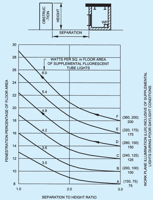
FIG. 4 NOMOGRAPH FOR DAYLIGHTING AND SUPPLEMENTAL LIGHTING DESIGN OF BUILDING
b) Step 2 — Fix the vertical line corresponding to the given separation to height ratio of opposite buildings on the abscissa. From the point of intersection of this vertical line and the above curve move along horizontal, and read the value of fenestration percent on the left hand ordinate.
c) Step 3 — If the floor area is greater than 50 m2 and less than 30 m2, the value of watts per square metre as well as fenestration percent may be easily determined for adequate daylighting and supplemental artificial lighting for design purposes. However, if the fenestration provided is less than the required value, the wattage of supplementary artificial
lights should be increased proportionately to make up for the deficiency of natural illumination.
4.4.4 For good distribution of day light on the working plane in a room, window height, window width and height of sill should be chosen in accordance with the following recommendations:
a) In office buildings windows of height 1.2 m or more in the center of a bay with sill level at 1.0 to 1.2 m above floor and in residential buildings windows of height 1.0 m to 1.1 m with sill height as 0.9 m to 0.7 m above floor are recommended for good distribution of daylight indoors. Window width can
accordingly be adjusted depending upon the required fenestration percentage of the floor area.
b) If the room depth is more than 10 m, windows should be provided on opposite sides for bilateral lighting.
c) It is desirable to have a white finish for ceiling and off white (light colour) to white for walls. There is about 7 percent improvement in lighting levels in changing the finish of walls from moderate to white.
4.4.5 For good distribution and integration of daylight with artificial lights the following guidelines are recommended:
a) Employ cool daylight fluorescent tubes for supplementary artificial lighting.
b) Distribute luminaries with a separation of 2 m to 3 m in each bay of 3 m to 4 m width.
c) Provide more supplementary lights such as twin tube luminaries in work areas where daylight is expected to be poor for example in the rear region of a room having single window and in the central region of a room having windows on opposite walls. In the vicinity of windows only single tube luminaries should be provided.
Energy conservation in lighting is effected by reducing wastage and using energy effective lamps and luminaires without sacrificing lighting quality. Measures to be followed comprise utilization of daylight, energy effective artificial lighting design by providing required illumination where needed, turning off artificial lights when not needed, maintaining lighter finishes of ceiling, walls and furnishings, and implementing periodic schedule for cleaning of luminaires and group replacement of lamps at suitable intervals. Choice of light sources with higher luminous efficacy and luminaires with appropriate light distribution is the most effective means of energy saving in lighting. However, choice of light sources also depends on the other lighting quality parameters like colour rendering index and colour temperature or appearance. For example, high pressure sodium vapour lamps, which have very high luminous efficacy, are not suitable for commercial interiors because of poor colour rendering index and colour appearance, but are highly desirable in heavy industries. Also the choice of light sources depends on the mounting height in the interiors. For example, fluorescent lamps are not preferred for mounting beyond 7 m height, when high pressure gas discharge lamps are preferred because of better optical control due to their compact size.
Luminous efficacy of some of the lamps used in lighting of buildings are given in Table 8 along with average life in burning hours, Colour Rendering Index and Colour Temperature.
Following recommendations may be followed in the choice of light sources for different locations:
a) For supplementary artificial lighting of work area in office building care should be taken to use fluorescent lamps, which match with colour temperature of the daylight.
b) For residential buildings fluorescent lamps and/or CFLs of proper CRI and CCT are recommended to match with the colours and interior design of the room.
c) For commercial interiors, depending on the mounting heights and interior design, fluorescent lamps, CFLs and low wattage metal halilde lamps are recommended. For highlighting the displays in show windows, hotels, etc, low wattage tubular or dichroic reflector type halogen lamps can be used.
d) For industrial lighting, depending on the mounting height and colour consideration fluorescent lamps, high pressure mercury vappour lamps or high pressure sodium vapour lamps are recommended.
4.4.6.2 For the same lumen output, it is possible to save 75 to 80 percent energy if GLS lamps are replaced with CFL and 65 to 70 percent if replaced with fluorescent lamps. Similar energy effective solutions are to be chosen for every application area.
Similarly with white fluorescent tubes recommended for corridors and staircases, the electrical consumption reduces to 1/4.5 of the energy consumption with incandescent lamps.
4.4.6.3 Efficient luminaire also plays an important role for energy conservation in lighting. The choice of a luminaire should be such that it is efficient not only initially but also throughout its life. Following luminaries are recommended for different locations:
a) For offices semi-direct type of luminaries are recommended so that both the work plane illumination and surround luminance can be effectively enhanced.
b) For corridors and staircases direct type of luminaries with wide spread of light distributions are recommended.
c) In residential buildings, bare fluorescent tubes are recommended. Wherever the incandescent lamps are employed, they should be provided
| Table 8 Luminous Efficacy, Life, CRI and CCT of Light Sources(Clause 4.4.6.1) | |||||
| Sl No. | Light Source | Efficacy lm/W | Average Life h | CRI | CCT K |
| (1) | (2) | (3) | (4) | (5) | (6) |
| i) | Incandescent lamps GLS 25 W-1 000 W | 8-18 | 1 000 | 100 | 2 800 |
| ii) | Tungsten halogen incandescent lamps Mains-voltage types: 60 W-2 000 W | 10% higher than comparable GLS lamp | 2 000 | 100 | 2 800-3 200 |
| Low-voltage types with reflector have lower wattages | |||||
| iii) | Fluorescent lamps (FTL) | ||||
| a) Standard lamps 38 mm (T12) | |||||
| 20 W-65 W | |||||
| 26 mm (T 8) | |||||
| 18 W-58 W | |||||
| Cool daylight | 61 | 5 000 | 72 | 6 500 | |
| Warm white | 67 | 5 000 | 57 | 3 500 | |
| b) Tri-Phosper lamps 38 mm (T12) | |||||
| 20 W-65 W | 88-104 | 12 000-18 000 | 85-95 | 2 700-6 500 | |
| 26 mm (T 8) | |||||
| 18 W-58 W | |||||
| iv) | Compact Fluorescent Lamps (CFL) 5 W-25 W | 40-80 | 8 000 | Similar to FTL | |
| v) | High pressure mercury vapour lamps 80 W-400 W | 36-60 | 5 000 | 45 | 4 000 |
| vi) | Blended — Light lamps MLL 100 W-500 W | 11-26 | 5 000 | 61 | 3 600 |
| vii) | High Pressure Sodium Vapour Lamps 50 W-1 000 W | 69-130 | 10 000-15 000 | 23 | 2 000 |
| viii) | Metal halide lamps 35 W-2 000 W | 69-83 | 10 000 | 68-92 | 3 000-5 600 |
| NOTES | |||||
| 1 The table includes lamps and wattages currently in use in buildings in India. | |||||
| 2 Luminous efficacy varies with the wattage of the lamp. | |||||
with white enamelled conical reflectors at an inclination of about 45° from vertical.
Adequate schedule for cleaning of window panes and luminaries will result in significant advantage of enhanced daylight and lumen output from luminaries. This will tend to reduce the duration over which artificial lights will be used and minimize the wastage of energy. Depending upon the location of the building a minimum of three to six months interval for periodic cleaning of luminaries and window panes is recommended for maximum utilization of daylight and artificial lights.
There is a considerable wastage of electrical energy in lighting of buildings due to carelessness in switching
off lights even when sufficient daylight is available indoors. In offices and commercial buildings, occupants may switch on lights in the morning and keep them on throughout the day. When sufficient daylight is available inside, suitable photo controls can be employed to switch off the artificial lights and thus prevent the wastage of energy.
Solar photovoltaic system enables direct conversion of sunlight into electricity and is viable option for lighting purpose in remote nongrid areas. The common SPV lighting systems are:
a) Solar lantern,
b) Fixed type solar home lighting system, and
c) Street lighting system.
4.4.9.1 SPV lighting system should preferably be provided with CFL for energy efficiency.
4.4.9.2 Invertors used in buildings for supplying electricity during the power cut period should be charged through SPV system.
4.4.9.3 Regular maintenance of SPV system is necessary for its satisfactory functioning.
3.1 The chief aim of orientation of buildings is to provide physically and psychologically comfortable living inside the building by creating conditions which suitably and successfully ward off the undesirable effects of severe weather to a considerable extent by judicious use of the recommendations and knowledge of climatic factors.
3.2.1 For the purpose of design of buildings, the country may be divided into the major climatic zones as given in Table 2, which also gives the basis of this classification.
| Table 2 Classification of Climate (Clause 3.2.1) |
|---|
| Sl Climatic Mean Monthly Mean Monthly No. Zone Maximum Relative Humidity Temperature (°C) Percentage(1) (2) (3) (4) |
| i) Hot-Dry above 30 below 55 ii) Warm-Humid above 30 above 55 above 25 above 75 iii) Temperate between 25-30 below 75 iv) Cold below 25 All values v) Composite see 3.2.2 |
The climatic classification map of India is shown in Fig. 2.
3.2.2 Each climatic zone does not have same climate for the whole year; it has a particular season for more than six months and may experience other seasons for the remaining period. A climatic zone that does not have any season for more than six months may be called as composite zone.
From the point of view of lighting and ventilation, the following climatic factors influence the optimum orientation of the building:
a) solar radiation and temperature
b) relative humidity, and
c) prevailing winds.
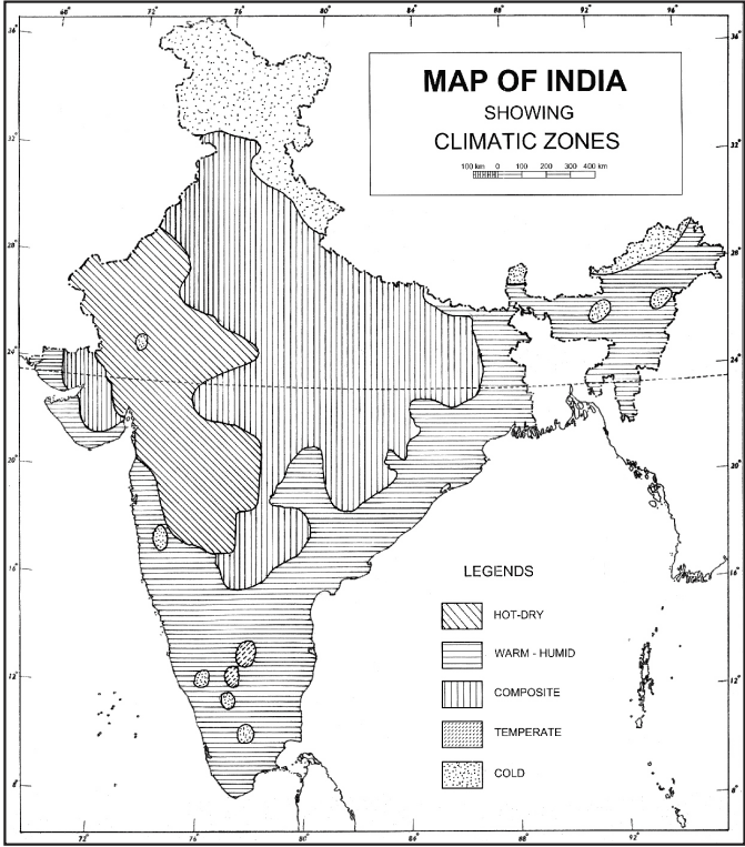
Based upon Survey of India Outline Map printed in 1993.
© Government of India Copyright, 2005
The territorial waters of India extend into the sea to a distance of twelve nautical miles measured from the appropriate base line.
The boundary of Meghalaya shown on this map is as interpreted from the North-Eastern Areas (Reorganisation) Act, 1971, but has yet to be verified.
Responsibility for correctness of internal details shown on the map rests with the publisher.
The state boundaries between Uttaranchal & Uttar Pradesh, Bihar & Jharkhand and Chhatisgarh & Madhya Pradesh have not been verified by Governments concerned.
FIG. 2 MAP OF INDIA SHOWING CLIMATIC ZONE
3.4.1 The best orientation from solar point of view requires that the building as a whole should receive the maximum solar radiation in winter and the minimum in summer. For practical evaluation, it is necessary to know the duration of sunshine, and hourly solar intensity on the various external surfaces on representative days of the seasons. The total direct plus diffused diurnal solar loads per unit area on vertical surface facing different directions are given in Table 3 for two days in the year, that is, 22 June and 22 December, representative of summer and winter, for latitudes corresponding to some important cities all over India. From Table 3, the total heat intake can be calculated for all possible orientations of the building for these extreme days of summer and winter.
3.4.1.1 Except in cold climatic zone, suitable sunbreakers have to be provided to cut off the incursion of direct sunlight to prevent heat radiation and to avoid glare.
3.5.1 The discomfort due to high relative humidity in air when temperatures are also high can be counteracted, to a great extent, by circulation of air with electric fans or by ventilation. In the past, simultaneously with heavy construction and surrounding VERANDAHS to counter the effect of sun’s radiation, there was also an over emphasis on prevailing winds to minimize the adverse effects of
high humidity with high temperatures. With the introduction of electric fan to effectively circulate air and owing to taking into account the rise in cost of construction of buildings, it would perhaps be better to shift the emphasis on protection from solar radiation where temperatures are very high. When, however, there is less diurnal variation between morning and mean maximum temperatures along with high humidity, as in coastal areas, the emphasis should be on prevailing winds.
3.5.1.1 For the purpose of orientation, it is necessary to study the velocity and direction of the wind at each hour and in each month instead of relying on generalizations of a month or a period or for the year as a whole. This helps to spot the right winds for a particular period of day or night.
3.5.1.2 It is generally found that variation up to 30° with respect to the prevalent wind direction does not materially affect indoor ventilation (average indoor air speed) inside the building.
3.5.2 In hot-dry climate, advantage can be taken of evaporative cooling in summer to cool the air before introducing it into the building. But in warm humid climate, it is desirable either to regulate the rate of air movement with the aid of electric fans or to take advantage of prevailing winds.
Since the clear design sky concept for daylighting takes care of the worst possible situation, orientation is not
| Orientation | Latitude | ||||||
| (1) | (2) | 9°N(3) | 13°N(4) | 17°N(5) | 21°N(6) | 25°N(7) | 29°N(8) |
| North | Summer | 1 494 | 1 251 | 2 102 | 1 775 | 2 173 | 1 927 |
| Winter | 873 | 859 | 840 | 825 | 802 | 765 | |
| North-East | Summer | 2 836 | 2 717 | 3 144 | 3 092 | 3 294 | 3 189 |
| Winter | 1 240 | 1 158 | 1 068 | 1 001 | 912 | 835 | |
| East | Summer | 3 344 | 3 361 | 3 475 | 3 598 | 3 703 | 3 794 |
| Winter | 2 800 | 2 673 | 2 525 | 2 409 | 2 211 | 2 055 | |
| South-East | Summer | 2 492 | 2 660 | 2 393 | 2 629 | 2 586 | 2 735 |
| Winter | 3 936 | 3 980 | 3 980 | 3 995 | 3 892 | 3 818 | |
| South | Summer | 1 009 | 1 185 | 1 035 | 1 117 | 1 112 | 1 350 |
| Winter | 4 674 | 4 847 | 4 958 | 5 059 | 4 942 | 4 981 | |
| South-West | Summer | 2 492 | 2 660 | 2 393 | 2 629 | 2 586 | 2 735 |
| Winter | 3 936 | 3 980 | 3 980 | 3 995 | 3 892 | 3 818 | |
| West | Summer | 3 341 | 3 361 | 3 475 | 3 598 | 3 703 | 3 794 |
| Winter | 2 800 | 2 673 | 2 525 | 2 409 | |||
Planting of trees in streets and in open spaces should be done carefully to take advantage of both shades and sunshine without handicapping the flow of natural winds. Their advantage in abating glare and in providing cool and/or warm pockets in developed areas should also be taken. Some trees shed leaves in winter while retaining thick foliage in summer. Such trees will be very advantageous, particularly where southern and western exposures are concerned, by allowing maximum sun during winter and effectively blocking it in summer.
3.8 For detailed information regarding orientation of buildings and recommendations for various climatic zones of country, reference may be made to good practice [8-1(1)].
The primary source of lighting for daylighting is the sun. The light received by the earth from the sun consists of two parts, namely, direct solar illuminance and sky illuminance. For the purposes of daylighting design, direct solar illuminance shall not be considered and only sky illuminance shall be taken as contributing to illumination of the building interiors during the day.
4.2.1 The relative amount of sky illuminance depends on the position of the sun defined by its altitude, which in turn, varies with the latitude of the locality, the day of the year and the time of the day, as indicated in Table 5.
4.2.2 The external available horizontal sky illuminance (diffuse illuminance) values which are exceeded for about 90 percent of the daytime working hours may be taken as outdoor design illuminance values for ensuring adequacy of daylighting design. The outdoor design sky illuminance varies for different climatic regions of the country. The recommended design sky illuminance values are 6 800 lux for cold climate, 8 000 lux for composite climate, 9 000 lux for warm humid climate, 9 000 lux for temperate climate and 10 500 for hot-dry climate. For integration with the artificial lighting during daytime working hours an increase of 500 lux in the recommended sky design illuminance for daylighting is suggested.
4.2.3 The daylight factor is dependent on the sky luminance distribution, which varies with atmospheric conditions. A clear design sky with its non-uniform distribution of luminance is adopted for the purposes of design in this section.
| Table 5 Solar-Altitudes (to the Nearest Degree) for Indian Latitudes(Clause 4.2.1) | ||||||||||||||||||
| Period of Year | 22 June | 21 March and 23 September | 22 December | |||||||||||||||
| Hours of Day (Sun or Solar) | 07 00 | 08 00 | 09 00 | 10 00 | 11 00 | 12 00 | 07 00 | 08 00 | 09 00 | 10 00 | 11 00 | 12 00 | 07 00 | 08 00 | 09 00 | 10 00 | 11 00 | 12 00 |
| Latitude (1) | 17 00(2) | 16 00(3) | 15 00(4) | 14 00(5) | 13 00(6) | —(7) | 17 00(8) | 16 00(9) | 15 00(10) | 14 00(11) | 13 00(12) | —(13) | 17 00(14) | 16 00(15) | 15 00(16) | 14 00(17) | 13 00(118) | —(19) |
| 10°N | 18 | 31 | 45 | 58 | 70 | 77 | 15 | 30 | 44 | 59 | 72 | 80 | 9 | 23 | 35 | 46 | 53 | 57 |
| 13°N | 19 | 32 | 46 | 60 | 72 | 80 | 15 | 29 | 44 | 58 | 70 | 77 | 8 | 21 | 33 | 43 | 51 | 54 |
| 16°N | 20 | 33 | 47 | 61 | 74 | 83 | 14 | 29 | 43 | 56 | 68 | 74 | 7 | 19 | 31 | 41 | 48 | 51 |
| 19°N | 21 | 34 | 48 | 62 | 75 | 86 | 14 | 28 | 42 | 55 | 66 | 71 | 5 | 18 | 29 | 48 | 45 | 48 |
| 22°N | 22 | 35 | 49 | 62 | 75 | 89 | 14 | 28 | 41 | 53 | 64 | 68 | 4 | 16 | 27 | 36 | 42 | 45 |
| 25°N | 23 | 36 | 49 | 63 | 76 | 88 | 13 | 27 | 40 | 52 | 61 | 65 | 3 | 14 | 25 | 34 | 39 | 42 |
| 28°N | 23 | 36 | 49 | 63 | 76 | 86 | 13 | 26 | 39 | 50 | 59 | 62 | 1 | 13 | 23 | 31 | 37 | 39 |
| 31°N | 24 | 37 | 50 | 62 | 75 | 82 | 13 | 25 | 37 | 48 | 56 | 56 | — | 11 | 21 | 28 | 34 | 36 |
| 34°N | 25 | 37 | 49 | 62 | 73 | 79 | 12 | 25 | 36 | 46 | 53 | 56 | — | 9 | 18 | 26 | 31 | 33 |
Daylight factor is the sum of all the daylight reaching on an indoor reference point from the following sources:
a) The direct sky visible from the point,
b) External surfaces reflecting light directly (see Note 1) to the point, and
c) Internal surfaces reflecting and interreflecting light to the point.
NOTES
1 External surface reflection may be computed approximately only for points at the centre of the room, and for detailed analysis procedures are complicated and these may be ignored for actual calculations.
2 Each of the three components, when expressed as a ratio or percent of the simultaneous external illuminance on the horizontal plane, defines respectively the sky component (SC), the external reflected component (ERC) and the internal reflected component (IRC) of the daylight factor.
4.2.4.1 The daylight factors on the horizontal plane only are usually taken, as the working plane in a room is generally horizontal; however, the factors in vertical planes should also be considered when specifying daylighting values for special cases, such as daylighting on class-rooms, blackboards, pictures and paintings hung on walls.
Sky component for a window of any size is computed by the use of the appropriate table of Annex A.
a) The recommended sky component level should be ensured generally on the working plane at the following positions:
at a distance of 3 m to 3.75 m from the window along the central line perpendicular to the window,
at the centre of the room if more appropriate, and
at fixed locations, such as school desks, black-boards and office tables.
b) The daylight area of the prescribed sky component should not normally be less than half the total area of the room.
4.2.5.1 The values obtainable from the tables are for rectangular, open unglazed windows, with no external obstructions. The values shall be corrected for the presence of window bars, glazing and external obstructions, if any. This assumes the maintenance of a regular cleaning schedule.
The corrections for window bars shall be made by multiplying the values read from tables in Annex A
by a factor equal to the ratio of the clear opening to the overall opening.
Where windows are glazed, the sky components obtained from Annex A shall be reduced by 10 to 20 percent, provided the panes are of clear and clean glass. Where glass is of the frosted (ground) type, the sky components read from Annex A may be reduced by 15 to 30 percent. In case of tinted or reflective glass the reduction is about 50 percent. Higher indicated correction corresponds to larger windows and/or near reference points. In the case of openings and glazings which are not vertical, suitable correction shall be taken into account.
There is no separate correction, except that the values from tables in Annex A shall be read only for the unobstructed portions of the window.
The value of the sky component corresponding to the portion of the window obstructed by the external obstructions may be found by the use of methods described in Annex B of good practice [8-1(3)].
These values when multiplied by the correction factors, corresponding to the mean elevation of obstruction from the point in question as given in Table 6, can be taken as the external reflected components for that point.
| Mean Angle of Elevation Correction Factor(1) (2) |
|---|
| 5° 0.08615° 0.08625° 0.14235° 0.19245° 0.22655° 0.27465° 0.30475° 0.32485° 0.334 |
4.2.6.1 For method of calculating ERC, reference may be made to accepted standard (see Examples 10 and 11 given in Annex B of good practice [8-1(3)].
The component of daylight factor contributed by reflection from the inside surfaces varies directly as the window area and inversely as the total area of internal surfaces, and depends on the reflection factor of the floor, wall and roof surfaces inside and of the
ground outside. For rooms white-washed on walls and ceiling and windows of normal sizes, the IRC will have sizeable value even at points far away from the window. External obstructions, when present, will proportionately reduce IRC. Where accurate values of IRC are desired, the same may be done in accordance with the good practice [8-1(3)].
4.2.8 General Principles of Openings to Afford Good Lighting
4.2.8.1 Generally, while taller openings give greater penetrations, broader openings give better distribution of light. It is preferable that some area of the sky at an altitude of 20° to 25° should light up the working plane.
4.2.8.2 Broader openings may also be equally or more efficient, provided their sills are raised by 300 mm to 600 mm above the working plane.
NOTE — It is to be noted that while placing window with a high sill level might help natural lighting, this is likely to reduce ventilation at work levels. While designing the opening for ventilation also, a compromise may be made by providing the sill level about 150 mm below the head level of workers.
4.2.8.3 For a given penetration, a number of small openings properly positioned along the same, adjacent or opposite walls will give better distribution of illumination than a single large opening. The sky component at any point, due to a number of openings may be easily determined from the corresponding sky component contour charts appropriately superposed. The sum of the individual sky component for each opening at the point gives the overall component due to all the openings. The same charts may also facilitate easy drawing of sky component contours due to multiple openings.
4.2.8.4 Unilateral lighting from side openings will, in general, be unsatisfactory if the effective width of the room is more than 2 to 2.5 times the distance from the floor to the top of the opening. In such cases provision of light shelves is always advantageous.
4.2.8.5 Openings on two opposite sides will give greater uniformity of internal daylight illumination, especially when the room is 7 m or more across. They also minimize glare by illuminating the wall surrounding each of the opposing openings. Side openings on one side and clerestory openings on the opposite side may be provided where the situation so requires.
4.2.8.6 Cross-lighting with openings on adjacent walls tends to increase the diffused lighting within a room.
4.2.8.7 Openings in deep reveals tend to minimize glare effects.
4.2.8.8 Openings shall be provided with CHAJJAHS, louvers, baffles or other shading devices to exclude,
as far as possible, direct sunlight entering the room. CHAJJAHS, louvers, etc, reduce the effective height of the opening for which due allowance shall be made. Broad and low openings are, in general, much easier to shade against sunlight entry. Direct sunlight, when it enters, increases the inside illuminance very considerably. Glare will result if it falls on walls at low angles, more so than when it falls on floors, especially when the floors are dark coloured or less reflective.
Proper planning and layout of building can add appreciably to daylighting illumination inside. Certain dispositions of building masses offer much less mutual obstruction to daylight than others and have a significant relevance, especially when intensive site planning is undertaken. The relative availability of daylight in multi-storeyed blocks of different relative orientations are given in Table 7.
| Distance of Infinitely Parallel Blocks Parallel Blocks Separation Long Facing Each Facing Gaps Between Parallel Other Between Opposite Blocks Blocks (Length = Blocks (Length = 2 × Height) 2 × Height)(1) (2) (3) (4) |
|---|
| 0.5 Ht 0.15 0.15 0.25 1.0 Ht 0.30 0.32 0.38 1.5 Ht 0.40 0.50 0.55 2.0 Ht 0.50 0.60 0.68 |
4.2.10 For specified requirements for daylighting of special occupancies and areas, reference may be made to good practice [8-1(4)].
The following publication has also been referred to in the preparation of this Section:
Report on energy conservation in buildings, submitted to Department of Power, Ministry of Energy by Central Building Research Institute, Roorkee.
All standards, whether given herein above or cross-referred to in the main text of this Section, are subject to revision. The parties to agreement based on this Section are encouraged to investigate the possibility of applying the most recent editions of the standards.
| 3 Average life values are from available Indian Standards. Where Indian Standard is not available, values given are only indicative. |
| 4 CRI and CCT values are only indicative. |
| 5 For exact values, it is advisable to contact manufacturers. |
| 2 211 |
| 2 055 |
| North-West | Summer | 2 836 | 2 717 | 3 144 | 3 092 | 3 294 | 3 189 |
| Winter | 1 240 | 1 158 | 1 068 | 1 001 | 912 | 835 |
| Horizontal | Summer | 8 107 | 8 139 | 8 379 | 8 553 | 8 817 | 8 863 |
| Winter | 6 409 | 6 040 | 5 615 | 5 231 | 4 748 | 4 281 |
a major problem for daylighting in buildings, except that direct sunshine and glare should be avoided. However, due allowance should be given to the mutual shading effects of opposite facades.
4.2.8.9 Light control media, such as translucent glass panes (opal or matt) surfaced by grinding, etching or sandblasting, configurated or corrugated glass, certain types of prismatic glass, tinted glass and glass blasts are often used. They should be provided, either fixed or movable outside or inside, especially in the upper portions of the openings. The lower portions are usually left clear to afford desirable view. The chief purpose of such fixtures is to reflect part of the light on to the roof and thereby increase the diffuse lighting within, light up the farther areas in the room and thereby produce a more uniform illumination throughout. They will also prevent the opening causing serious glare discomfort to the occupants but will provide some glare when illuminated by direct sunlight.