This Section covers requirements of landscape planning and design with the view to promoting quality of outdoor built environment and protection of land and its resources.
Loading…
Any development project for which a permit or licence
is required, shall make application to the Authority on the prescribed form containing such particulars as the Authority may require. The form shall be signed by the owner and shall include the information given in 3.2 to 3.4. For various aspects of obtaining the permit, etc reference shall be made to Part 2 ‘Administration’.
The site plan to be submitted with the application for permit shall be drawn to a scale of not less than 1 in 500 for a site up to one hectare and not less than 1 in 1 000 for site more than 10 hectare. The following information shall be provided in addition to requirements for Site Plan as stated in Part 2 'Administration':
a) Existing and proposed topographic contours at interval not exceeding 50 cm and/or spot elevations as pertinent and Bench Mark of site with reference to the City Datum relative to the Mean Sea Level.
b) Limits of the 100 year flood plain and water surface elevation (when applicable).
c) Location of existing major physical features, such as railway track, drainage ways etc.
d) Location of service utilities adjacent to the project with relevant top and invert levels clearly indicated.
e) Point of egress and ingress including locations and width of road.
f) Fully dimensioned loading spaces and maneuvering areas.
g) Parking including, location, parking spaces, size and number, and typical parking space details for both handicapped and standard spaces.
h) Vehicular, bicycle, pedestrian and handicapped circulation clearly identified.
j) Detail for parking areas including type of lighting, material for paving, and security rooms, rest rooms; and type of directional signage etc.
k) Drainage system, proposed finish ground elevations and finish grades.
m) Location of proposed fire hydrant points.
n) Location and dimension of fire lanes.
p) Proposed lighting layout.
q) Landscape irrigation points and source of water.
r) Fences, walls, or vegetation for screening by type, material, height, location, and spacing.
s) Location of proposed street furniture.
t) Refuse container location, size, and access.
u) Landscape paving materials with location.
v) Location, type, size, and height of existing and proposed signage.
w) List of existing trees with botanical and common names and height of the tree (see 4.1.2 for plant material schedule).
x) Prior approvals.
Landscape plan and drawings shall consist of the plans and details as given in 3.3.1 to 3.3.4.
The grading plan to be submitted with the application for permit shall be drawn to a scale of not less than 1 in 500 for a site up to 10 hectare and not less than 1 in 1 000 for site more than 10 hectare (see also 6.2). The grading plan will include measures for soil and sedimentation control and also measures during construction to prevent soil erosion, and also water harvesting practices (see also 4 and 5).
The planting plan shall be drawn to a scale of not less than 1 in 200 for a site up to one hectare and not less than 1 in 500 for site more than 10 hectare with part plans at 1 in 200 of two of the design areas. Planting plan should include plant material schedule as shown in Table 1. The planting plan and landscape plan must show identical information to avoid conflict between both plans. The planting plan shall include the layouts as given below drawn to the scale:
a) Location of proposed trees, shrubs, ground covers and lawn area indicated clearly with appropriate symbols and legend.
b) The size of plant material indicated in the drawing should be shown as diameter of canopy for tree and spread for shrubs and ground cover. Two years growth will be considered as full maturity size for shrubs and ground covers and ten years growth will be considered for trees.
c) The Botanical name could be indicated as a symbol on the main drawing (for example Delonix regia as Dr). Plant names should to be tabulated in alphabetical order under heads Trees, Shrubs, Groundcovers, Climbers and Grass.
d) Functional attributes and growth pattern tabulation to be attached as Table 2, as an annex.
e) All existing vegetation shall be marked on the landscape plan and areas designated for
preservation of existing vegetation on site shall be demarcated clearly (see also 4.1.2).
f) A concept plan of scale not less than 1 in 1 000 indicating the intent of the design with respect to the functions for various parts of the scheme should be included.
| Tree No. | Code | Botanical Name | Common Name | Quantity |
|---|---|---|---|---|
| (1) | (2) | (3) | (4) | (5) |
2.0 For the purpose of this Section, the following definitions shall apply.
2.1 Avenue — A wide road or pathway lined with trees on either sides.
2.2 Buffer — The use of landscape to curtail view, sound or dust with plants or earth berms, wall, or any such element.
2.3 Climber (Creeper/Vine) — A non-supporting plant, woody or herbaceous, which clings to a wall, trellis or other structures as it grows upward.
2.4 Columnar — A slender, upright plant form.
2.5 Contour — The form of the land, existing or proposed; a part of the topography, indicated by map lines at intervals as desired, to understand the landform clearly. The contour line though imaginary, indicates continuous elevation above mean sea level or an assumed datum line.
2.6 Contour Interval — The difference in elevation or the vertical distance measured between consecutive contour lines.
2.7 Egress — A way out, or exit.
2.8 Elevation — A contour line or notation of relative altitude, useful in plotting existing or proposed feature.
2.9 Exotic — A plant that is not native to the area in which it is planted.
5
2.10 Fencing — A barrier of plant or construction material used to set off the boundary of an area and to restrict visual or physical passage in or out of it.
2.11 Foliage — The collective leaves of a plant or plants.
2.12 Geo-textile — Any permeable textile (natural or synthetic) used with foundation, soil, rock, earth or any other geotechnical engineering-related material as an integral part of a human made project, structure or system.
2.13 Grade — The slope or lay of the land as indicated by a related series of elevations.
2.13.1 Natural Grade — Grade consisting of contours of unmodified natural landform.
2.13.2 Finished Grade — Grade accomplished after landscape features are installed and completed as shown on plan as proposed contours.
2.14 Gradient — The degree of slope of a pipe invert or road or land surface. The gradient is a measure of the slope height as related to its base. The slope is expressed in terms of percentage or ratio.
2.15 Grading — The cutting and/or filling of earth to establish smooth finish contours for a landscape construction project. Grading facilitates good drainage and sculpts land to suit the intent of landscape design.
2.16 Grasses — Plants that characteristically have joint stems, sheaths and narrow blades (leaves).
2.17 Groundcover — The planting material that forms a carpet of low height; these low-growing plants are usually installed as the final part of landscape construction.
2.18 Hard Landscape — Civil work component of landscape architecture such as pavement, walkways, roads, retaining walls, sculpture, street amenities, fountains and other built environment.
2.19 Hardy Plant — Plants that can withstand harsh temperature variations, pollution, dust, extreme soil conditions, and minimal water requirements and the likes. These plants have ability to remain dormant in such conditions and survive.
2.20 Hedge — Number of shrubs or trees (often similar species) planted closely together in a line. A hedge may be pruned to shape or allowed to grow to assume its natural shape.
2.21 Herb — An annual plant with a non-woody or fleshy structure. Certain herbs are highly useful for cooking or of high medicinal value.
2.22 Ingress — A way in, or entrance.
2.23 Invert — The low inside point of a pipe, culvert, or channel.
2.24 Kerb — A concrete or stone edging along a pathway or road often constructed with a channel to guide the flow of storm water and thereby serving dual purpose.
2.25 Mound — A small hill or bank of earth, developed as a characteristic feature in landscape.
2.26 Native — A plant indigenous to a particular locale.
2.27 Screen — A vegetative or constructed hedge or fence used to block wind, undesirable views, noise, glare and the like, as part of in landscape design; also known as ‘screen planting’ and ‘buffer plantation’.
2.28 Sediment — The product of erosion processes; the solid material, both mineral and organic, that is in suspension, is being transported or has been moved from its site of origin by air, water, gravity or ice.
2.29 Shrub — A woody plant of low to medium height, deciduous or evergreen, generally having many stem.
2.30 Soft Landscape — The natural elements in landscape design, such as plant materials and the soil itself.
2.31 Spot Elevation — In surveying and contour layout, an existing or proposed elevation noted as a dot on the plan.
2.32 Street/Outdoor Furniture — Items of furnishing in outdoor landscape.
2.33 Swale — A linear wide and shallow depression used to temporarily store, route or filter runoff. A swale may be grassed or lined.
2.34 Topsoil — The uppermost layer of the soil.
2.35 Transplanting — Moving a plant from its place of origin to another location.
2.36 Tree — A woody plant, generally taller than 2.00 m, with a well-distinguished trunk or trunks below the leaf crown.
2.36.1 Deciduous Tree — Tree that sheds all its leaves in autumn or in dry season.
2.36.2 Evergreen Tree — Tree that remains green for most part of the year and sheds leave slowly throughout the year.
2.37 Tree Grate — A metal grille, installed at the base of a tree otherwise surrounded by pavement, that allows the free passage of air, water, and nutrients to the tree root, but does not interfere with the foot traffic.
2.38 Tree/Plant Guard — The protection constructed around a tree to deter vandalism and help to prevent damage. It could be made of metal, bamboo or concrete or the like.
4.0 Development projects involve disturbance to the existing soil conditions, removal of existing trees and overall change in the microclimate and drainage pattern. Measures to minimize hazardous effects should be put into effect as explained below.
Measures for the prevention of soil erosion, sediment control and management of storm water shall be implemented as given in 4.1.1 to 4.1.5.
Construction work and erosion control applications shall be scheduled and sequenced during dry weather periods when the potential for erosion is the lowest. Slope protection techniques to control erosion shall be used when construction during wet season is unavoidable. Sedimentation collection systems, drainage systems, and runoff diversion devices shall be installed before construction activity. The Landscape Architect/Architect/Engineer-in-charge shall monitor the site conditions and progress of work and schedule appropriate timing and sequencing of construction.
4.1.2.1 Protection of existing vegetation (including trees, shrubs, grasses and other plants) where possible, by preventing disturbance or damage to specified areas during construction is recommended. This practice minimizes the amount of bare soil exposed to erosive forces. All existing vegetation shall be marked on a site survey plan. A tree survey in prescribed format shall be
carried out as indicated in Table 3. The landscape plan should indicate trees, which have been preserved, and also those, which had to be transplanted or removed clearly differentiating between these three categories.
| Tree No. | Botanical Name | Common Name | Girth | Height | Spread | Condition |
|---|---|---|---|---|---|---|
| (1) | (2) | (3) | (4) | (5) | (6) | (7) |
4.1.2.2 Trees retained on the project site shall be protected during the construction period by following measures:
a) Damage to roots shall be prevented during trenching, placing backfill, driving or parking heavy equipment, dumping of trash, oil, paint, and other materials detrimental to plant health by restricting these activities to outside the area of the canopy of the tree.
b) Trees will not be used for support; their trunks shall not be damaged by cutting and carving or by nailing posters, advertisements or other material.
c) Lighting of fires or carrying out heat or gas emitting construction activity within the ground, covered by canopy of the tree shall not be permitted.
d) Young trees or saplings identified for preservation (height less than 2.00 m, 0.10 m trunk girth at 1.00 m height from finish ground, 2.00 m crown diameter) within the construction site have to be protected using tree guards of approved specification.
Existing drainage patterns through or into any preservation area shall not be modified unless specifically directed by the Landscape Architect/Architect/Engineer-in-charge.
f) Existing grades shall be maintained around existing vegetation and lowering or raising the levels around the vegetation is not allowed unless specifically directed by the Landscape Architect/Architect/Engineer-in-charge.
g) Maintenance activities shall be performed as needed to ensure that the vegetation remains healthy.
h) The preserved vegetated area shall be inspected by the Landscape Architect/ Architect/Engineer-in-charge at regular intervals so that they remain undisturbed. The
date of inspection, type of maintenance or restorative action followed shall be recorded in the logbook.
Measures shall be followed for collecting runoff from construction areas and material storage sites; diverting water flow away from such polluted areas, so that pollutants do not mix with storm water runoff from undisturbed areas.
Temporary drainage channels, perimeter dike/swale, etc shall be constructed to carry the pollutant-laden water directly to treatment device or facility. The plan shall indicate how the above is accomplished on site, well in advance of the commencing of the construction activity.
Topsoil removal and preservation shall be mandatory for development projects larger than 1.00 hectare. Topsoil shall be stripped to a depth of 200 mm from areas proposed to be occupied by buildings, roads, paved areas and external services. Topsoil is rich in organic content and is essential to establish new vegetation. It shall be stockpiled to a height of 400 mm in designated areas and shall be re-applied to site during plantation of the proposed vegetation. Topsoil shall be separated from sub-soil debris and stones larger than 50 mm diameter. The stored topsoil may be used as finished grade for planting areas.
Spill prevention and control plans shall be made, clearly stating measures to stop the source of the spill, to contain the spill, to dispose the contaminated material and hazardous wastes, and stating designation of personnel trained to prevent and control spills. Hazardous wastes include pesticides, paints, cleaners, petroleum products, fertilizers and solvents.
During construction soil becomes unconsolidated due to removal of stabilizing material such as vegetation and disturbance of stabilized existing grade resulting in loss of topsoil and also deposition in undesirable places. A soil erosion and sedimentation control plan to be prepared prior to construction. The soil erosion, sediment control and storm water practices should be considered whilst construction is proceeding, in accordance with 4.2.1 to 4.2.4.
A temporary dam or basin at the lowest point of the site has to be constructed for collecting, trapping and storing sediment produced by the construction activities, together with a flow detention facility for
reducing peak runoff rates. This would allow most of the sediments to settle before the runoff is directed towards the outfall.
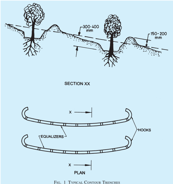
Contour trenching is an earth embankment or ridgeand-channel arrangement constructed parallel to the contours along the face of the slope at regular intervals on long and steep slopes (in sloping areas with slopes greater than 10 percent) (see Fig. 1). They are used for reducing runoff velocity, increasing the distance of overland runoff flow, and to hold moisture and minimize sediment loading of surface runoff. Vegetative cover of tree and native grasses in the channels may be planted to stabilize the slopes and reduce erosion.
Mulching shall be used with seeding and planting in steep slope areas (slopes greater than 33 percent) that are prone to heavy erosion. Netting or anchoring shall be used to hold it in place. Other surface runoff control measures like contour terracing to break up concentrated flows shall be installed prior to seeding and mulching. Materials such as straw, grass, grass hay and compost shall be placed on or incorporated into the soil surface. In addition to stabilizing soils, mulching will reduce the storm water runoff over an area. Together with seeding or planting, mulching aids plant growth by holding the seed, fertilizers and topsoil in place. It retains moisture and insulates the soil against extreme temperatures.
A deformed or non-deformed netlike polymeric material used with foundation, soil, rock, earth or any other geo-technical engineering-related material as an integral part of the human-made project structure or system, called geo-grids may be used as control measure. On filling with lightly compacted soil or fine aggregate, a monolithic structure is created providing an effective means of confinement for unconsolidated materials within the cells and preventing their movement even on steep slopes. If required the area can then be seeded to maintain ‘green’ environment. The junctions have a central opening through which water can permeate ensuring that organic material receives moisture for rapid growth.
Design for changes in elevation in the outdoor environment is a primary component of landscape development. Grading of proposed external development areas should relate to the existing topography of the site and it should direct surface water runoff to the designed drainage and water harvesting area. Grading design parameters are as follows:
a) The proposed grading design should respond to the function and purpose of the activities to be accommodated within the site.
b) New development and structures to be integrated with existing landform within the site and in its immediate surroundings.
c) Storm water to be directed away from buildings.
d) Terraces, levels and slopes in required areas to be created and to emphasize control, or negotiate circulation routes and views.
e) Steep slopes to be modified to minimize or eliminate erosion.
f) Legally, grades cannot be changed beyond the property line of the site.
g) The rate of storm water runoff leaving the site after construction to not exceed the pre-construction rate.
h) Grading design should optimize cut and fill.
6.2.1 The submitted grading plan should include the following:
a) All existing features of the site, including all building with plinth level;
b) Structures such as walls, walks, steps, roads, etc;
c) Utilities such as water lines, sewer and storm water drainage, electrical lines, etc; and
d) Utility structures like manholes, junction boxes, sewage treatment plant, septic tank, soak pit, water tanks, water treatment plant, transformers and all underground structures indicated appropriately.
Proposed features shall be indicated in firm lines and existing features in dash.
a) General landform concept graphically represented with appropriate symbols and abbreviations (see 6.4).
b) Proposed contour lines should be integrated with existing and proposed elevations within the project site.
c) Location of swales and surface water flow, surface and sub-surface soil drainage system or water harvesting systems.
d) Location of drainage catchments, areas of retention/detention or disposal/outfall point as the case may be.
e) Spot grades on road, walks, and swales including top level and relevant invert levels of all utilities and utilities structures as mentioned above; critical spot elevation to be established (see 6.2.3).
f) Spot elevation of building floor finish level, steps, walls, terraces and other such structures.
g) Changes in direction or rate of slope.
Spot elevations shall be used to supplement contours in the following situations:
a) To indicate variations from the normal slope or gradient between contour lines.
b) To indicate elevations of intersecting planes and lines, like corners of buildings, walls, steps and kerbs.
c) To indicate elevations at top and bottom of vertical elements like walls, steps and kerbs.
d) To indicate floor and entrance elevations.
e) To indicate elevations of high and low points.
f) To indicate top elevations of utilities and utilities structure.
Slopes are expressed as follows:
| Symbol | Description |
|---|---|
| --(100)-- | Existing contour |
| — 100 — | Proposed contour |
| (100.5) | Existing spot elevation |
| 100.5 (Bold) | Proposed spot elevation |
| CB | Catch basin |
| FFL | Finished floor level |
| FGL | Finished ground level |
| TW/BW | Top of wall/Bottom of wall |
| TK/BK | Top of kerb/Bottom of kerb |
| HP/LP | High point/Low point |
| IL | Invert level |
The soil conservation, sediment control and storm water management practices as given in 5.1 to 5.3 shall be followed after construction is completed.
The vegetative measures shall include the following:
This includes the placement of topsoil or other suitable plant material over disturbed lands to provide suitable soil medium for vegetative growth. Topsoil laying shall involve replacing fertile topsoils that were stripped and stockpiled during earlier site development activities; the laid soil shall be stabilized before the next monsoon by planting grass, shrubs and trees.
The following guidelines shall apply to the placement of topsoil:
a) The existing or established grade of sub-soil should be maintained.
b) A pH of 6.0 to 7.5 and organic content of not less than 1.5 percent by mass is recommended for topsoil. Where pH is less than 6.0, lime shall be applied to adjust pH to 6.5 or higher up to 7.5. Any soils having soluble salt content greater than 500 parts per million shall not be used.
c) Prior to spreading the topsoil, the sub-grade shall be loosened to a depth of 50 mm to permit bonding. Topsoil shall be spread uniformly at a minimum compacted depth of 50 mm on grade of 1:3 or steeper slopes; a minimum depth of 100 mm on shallower slopes is essential. A depth of 300 mm is preferred on relatively flatter land.
The most effective way to prevent soil erosion, sedimentation and to stabilize disturbed and undisturbed land is through the provision of vegetative cover by effective planting practices. The foliage and roots of plants provide dust control and a reduction in erosion potential by increasing the infiltration, trapping sediment, stabilizing soil, and dissipating the energy of hard rain. Temporary seeding shall be used in areas disturbed after rough grading to provide soil protection until final cover is established. Permanent seeding/
planting is used in buffer areas, vegetated swales and steep slopes. The vegetative cover also increases the percolation of rain-water thereby increasing the ground water recharge.
The surface water flow is increased in urban areas due to predominance of hard surfaces. Storm water management techniques assure conservation of water thereby increasing the ground water recharge. Filters facilitate draining pollutants out from surface water runoff through straining before discharge into the drainage way. Rain-water harvesting and sullage recycle systems need to be implemented on all new constructions over 1 000 m2 in urban areas (see also Part 9 ‘Plumbing Services, Section 1 Water Supply, Drainage and Sanitation’).
5.2.1.1 Water harvesting refers to the collection and storage of rain-water and also harvesting surface and ground water, prevention of loss through evaporation and seepage, and other hydrological and engineering interventions aimed at conserving water.
a) Water harvesting recharges ground water and is an ideal solution to water problems in areas with inadequate water resources.
b) Increase in ground water aquifer level due to methods enhancing infiltration.
c) Mitigation of the effect of drought.
d) Reduction of storm water runoff into the public drainage system.
e) Reduction of flooding of the roads during monsoons.
f) Removal of pollutants and soil from the storm water runoff.
g) Reduction of soil erosion.
a) Recharge pits,
b) Recharge trenches,
c) Re-use of abandoned dug wells,
d) Re-use of abandoned hand pumps,
e) Recharge shafts,
f) Lateral shafts with bore wells, and
g) Spreading techniques like percolation ponds, check dams or gabion structures.
These may be as given in 5.2.2.1 and 5.2.2.2.
a) Infiltration trenches — An infiltration trench is a rock filled trench that receives storm water runoff. Storm water passes through a combination of pre-treatment measures, a grass swale and into the trench to be stored in void spaces and then infiltrates into the soil matrix.
b) Bio-filtration swale/grass swale — Biofiltration swales are vegetated channels with a slope similar to that of standard storm drain channels (less than 0.6 percent), but wider and shallower to maximize flow residence time and promote pollutant removal by filtration through the use of properly selected vegetation. It has to be designed to trap particulate pollutants (suspended solids and trace metals), promote infiltration and reduce the flow velocity of the storm water runoff. It shall be integrated with storm water system (see Fig. 2).
The following measures shall be followed for design of irrigation systems for landscape works:
a) Water conserving irrigation systems should differentiate between systems for different water use zones on the site. Supplementary irrigation sources should be used by means of appropriate water harvesting measures.
b) The irrigation system should be designed considering the prevailing wind direction, slope and proposed grade, type of soil, soil percolation, and the type of vegetation to be watered.
c) Spray irrigation to be designed to provide total head to head cover to avoid dry spots and spray on to paved areas and unplanted surfaces.
d) Spray irrigation is to be avoided in areas of width less than 3.00 m.
e) Sullage recycle systems are ideal for large housing complexes and residential colonies. Sullage (or water from kitchens and bathrooms) is treated and recycled for gardening and toilet flushing reducing fresh water requirement by 60 percent. Irrigation system should be designed keeping sullage recycle in view.
f) For requirements regarding, the volume of water for different kinds of landscapes, see Part 9 ‘Plumbing Services, Section 1 Water
Supply, Drainage and Sanitation’ may be referred.
| Sl No. | Relevant Features | Description Plant -1 |
|---|---|---|
| (1) | (2) | (3) |
| i) | Botanical name | |
| ii) | Common name | |
| iii) | Plant code | |
| iv) | Type (Evergreen/Deciduous) | |
| v) | Height | |
| vi) | Spread/Canopy | |
| vii) | Form of Tree | |
| viii) | Flower colour | |
| ix) | Seasonal duration | |
| x) | Zone (Functional Attributes) | |
| xi) | Characteristics | |
| xii) | Function | |
| xiii) | Remarks |
The irrigation plan shall be drawn to a scale of not less than 1 in 500 for a site up to one hectare and not less than 1 in 1 000 for site more than one hectare. The Plan shall include the following information:
a) The source of irrigation water.
b) Type of water conserving irrigation systems proposed differentiating between systems for different water use zones on the site.
c) Extent of supplementary irrigation provided by water harvesting measures.
d) Arrangement of hydrants or sprinklers indicating location and type with typical details and specifications.
Construction details, specifications and methods used for the following landscape elements are to be included where applicable:
a) All paved areas for pedestrian and vehicular use, including edges, kerbs, bumper stops, steps, ramps, planters, railings or other protective devices; provision for wheel chair access and movement; Tree protection with tree grating, tree guard, etc.
b) Boundary wall, fence, retaining wall, etc.
c) Structures in landscape such as gatehouses, kiosks, toilets, pergolas, space frame, pools, ponds, water bodies, any other special features, etc.
d) Site utilities such as stormwater drains, manholes, catch basins, outdoor lighting fixtures, electric feeder pillars, junction box, fire hydrant, garbage collection points, litter bins, etc.
e) Outdoor signage and street furniture.
f) Play equipment and tot lots where appropriate.
g) Any other relevant detail or information.
c) Degree of slope, expressed as angle for example 10°, 15°, etc.
c) Sand filter — Sand filters are devices that filter storm water runoff through a sand layer into an underground drain system which conveys the water to a detention facility. They are effective in removing total suspended solids. The effectiveness of sand filtration is improved if it is preceded by a grass swale with infiltration trench.
a) Wet ponds — Wet ponds are constructed basins that have a permanent pool of water throughout the year (or at least throughout the wet season). Wet ponds retain the storm water runoff in a permanent pool and facilitate pollution removal through settling and biological update.
b) Storm water wet lands — Storm water wet lands are structures similar to wet ponds, that incorporate wetland plants into the design. They have to be designed for treating storm water runoff, and typically have less biodiversity than natural wetland systems. A distinction should be made between using a constructed wet land for storm water management and diverting storm water into natural wetland. The latter is not recommended because it would degrade the resource.
c) Wet vaults and storage tanks — Wet vaults
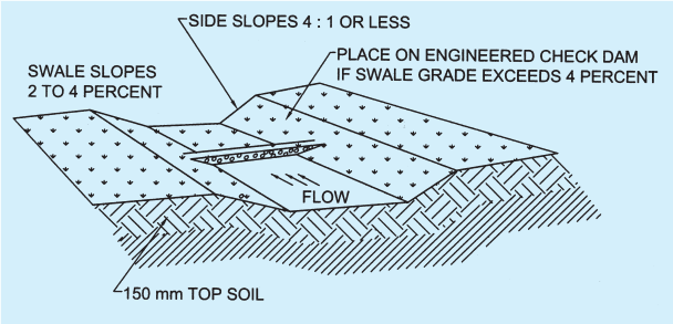
FIG. 2 GRASS SWALE
and tanks are underground facilities used for the storage of surface water, and typically constructed from reinforced cement concrete (vaults) or corrugated pipes (tanks). The water that is captured in these vaults and tanks may be used later for irrigation.