Fire Detection and Alarm System: A system comprising components and sub-systems required for automatically detecting smoke, heat or fire initiating an alarm and other actions as appropriate. This system also includes manually operated electronic fire alarm (MOEFA1) system.
2 Combustible Material: A material which either burns itself or adds heat to a fire, when tested for non-combustibility in accordance with accepted standard.
3 Down-comer: An arrangement of firefighting within the building by means of down-comer pipe connected to terrace tank through terrace pump, gate valve and non-return valve and having mains not less than 100 mm internal diameter with landing valves on each floor/landing. It is also fitted with inlet connections at ground level for charging with water by pumping from fire service appliances and air release valve at roof level to release trapped air inside.
1 MOEFA system (with or without automatic fire detection and alarm system) includes all or some of the components such as manual call stations (initiating an alarm for fire and other actions as required), talk-back system and public address system.
Page No 7
4 Dry Riser: An arrangement of firefighting within the building by means of vertical rising mains not less than 100 mm internal diameter with landing valves on each floor/landing which is normally dry but is capable of being charged with water usually by pumping from fire service appliances.
5 Emergency Lighting: Lighting provided for use when the supply to the normal lighting fails.
6 Emergency Lighting System: A complete but discrete emergency lighting installation also fed from the standby power source to the emergency lighting lamp(s), for example, self-contained emergency luminaire or a circuit from central battery (with or without monitoring system) connected through wiring to several escape lighting luminaries.
7 Escape Lighting: That part of the emergency lighting which is provided to ensure that the escape route is illuminated at all material times, for example, at all times when persons are on the premises, or at times the main lighting is not available, either for the whole building or for the means of egress.
8 Evacuation Lift: Lift that can be used, during an emergency, for self- evacuation.
9 Exit: means a passage, channel or means of egress from any building, storey or floor area to a street or other open space of safety. Exit components include exterior exit doors at the level of exit discharge, interior exit stairways, exit passageways, exterior exit stairways and exterior exit ramps.
a) Exit Access: That portion of a means of egress that leads to an exit (for example, doorways, staircase lobby, ramps, Veranda, corridor, or passageway leading to an exit. (Refer Figure No. 14.1).
b) Exit Access Corridor: A corridor in exit access which may not necessarily have the requirement of exits being met.
c) Exit Discharge: The component of a means of egress between the termination of an exit and a public way (Refer Figure. No. 14.1).
d) Horizontal exit: A defend in place or a staging arrangement, providing safety from fire and smoke originating from the area of incidence, by allowing alternative egress from a compartment to an area of refuge or another compartment at or near the same level. This also includes such egress from a compartment to an adjoining building. A horizontal exit shall be through a fire door of 120 min rating in a fire-resistant wall. Horizontal exits require separation with the refuge area or adjoining compartment through 120 min fire barrier. The adjoining compartment of the horizontal exit should allow unlocked and ease of egress and exits for the occupants using defend in place strategy.
d) Vertical Exit: means an exit used for ascending or descending between two or more levels, including stairways. smoke-proof towers, ramps, escalators, and fire escapes.
Page No 8
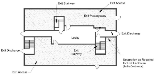
Figure No. 14.1: Components of Exit
10 Fire Barrier (or Fire Resisting Barrier): A fire barrier is a vertically or horizontally aligned member such as a wall or a fire curtain, or a floor. These may be with discontinuities created by openings with a specified fire resistance rating, where such members are designed and constructed with a specified fire resistance rating to limit the spread of fire that also restricts the movement of smoke.
11 Fire Compartment: A space within a building that is enclosed by fire barrier or fire-resistant walls on all sides, including the top and bottom.
12 Fire Door / Fire Resistant Door2: Any combination of fire door, frame, hardware, and other accessories that together provide a specific fire-resistant rating to the opening in terms of its stability, integrity, and insulation properties, when installed in the openings in fire separation walls.
13 Fire Exit: A way out leading from exit access with or without panic bar provided on the door.
14 Firefighting Shaft (Fire Tower): An enclosed shaft having protected area of 120 min fire resistance rating comprising protected lobby, staircase, and fireman’s lift, connected directly to exit discharge or through exit passageway with 120 min fire resistant wall at the level of exit discharge to exit discharge. These shall also serve the purpose of exit requirement/ strategy for the occupants. The respective floors shall be approachable from fire-fighting shaft enabling the fire fighters to access the floor and also enabling the fire fighters to assist in evacuation through fireman’s lift. The firefighting shaft shall be equipped with 120 min fire doors. The firefighting shaft shall be equipped with firemen talk back, wet riser and landing valve in its lobby, to fight fire by fire fighters. (see Figure 14.2 for a typical firefighting shaft).
2 NOTES
1 Fire doors in exits shall have fire rating as required in this Part/ these Rules to meet the requirement of integrity and stability; and the insulation criteria shall be 20 min.
2 Fire doors in exits shall be provided with intumescent seal.
3 Fire doors in exits shall not be allowed to be on hold open position and kept closed and to close by ‘door closure — spring mechanism’.
4 Fire curtains shall not be allowed as fire exits. If so provided for compartmentation, independent fire door shall be provided meeting the requirement for fire door in exits as above (of the width as required) within the prescribed travel distance requirement.
Page No 9
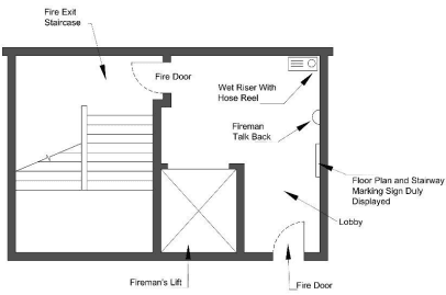
Figure No 14.2: Typical Fire Fighting Shaft
15 Fire Load: Calorific energy, of the whole contents contained in a space, including the facings of the walls, partitions, floors and ceilings.
16 Fire Load Density: Fire load divided by floor area.
17 Fire/Fireman’s Lift: A lift or a group of lifts invariably associated with all the features and requirements of a fire-fighting shaft. Such lift(s) are installed to enable fire services personnel to reach different floors with minimum delay and shall meet the additional features as required in accordance with these Rules. This lift also serves the purpose of meeting the requirement of evacuation lift for assisted evacuation.
18 Fire Resistance: Fire resistance is a property of an element of building construction and is the measure of its ability to satisfy for a stated period, some or all of the following criteria:
a) Load bearing capacity (Stability) (R) — The ability of a load bearing element to withstand fire exposure without any loss of structural stability.
b) Integrity (E) — Resistance to penetration of flame and hot gases (minimum 2 hours).
c) Insulation (I) — Resistance to temperature rise on the unexposed face up to a maximum of 180°C at any single point and average temperature of 140°C.
The fire resistance test of structures shall be done in accordance with IS: 3809-1966 Fire Resistance Test of Structure.
19 Fire Resistance Rating 3— The time that a material or construction will withstand the standard fire exposure as determined by fire test done in accordance with the standard methods of fire tests of materials/ structures as per the accepted standard (Refer Annexure K (2)).
20 Fire Resistant Wall: Fire resistance rated wall, having opening(s) with specified fire-resistant rating, which restricts the spread of fire from one part of a building to another part of the same building.
3 NOTES
1 The requirement of rating of various building elements as given in this Part shall be applicable in accordance with the provisions given in the accepted standard (Refer Annexure K (2))
2 The fire resistance rating shall be specified in terms of minutes.
3 Fire resistance rating for non-structural material/assembly shall bear a label of compliance to such rating as per the approval of competent authority based on testing and evaluation. The label shall be permanently affixed to the material/assembly and may carry other relevant details such as name and type of the product, and manufacturer’s details.
Page No 10
21 Fire Separation: The distance in metre, measured from the external wall of the building concerned to the external wall of any other building on the site, or from other site, or from the opposite side of street or other public space for the purpose of preventing the spread of fire.
22 Fire Stop 4: A fire resistant material, or construction, having a fire resistance rating of not less than the fire separating elements, installed in concealed spaces or between structural elements of a building to prevent the spread/propagation of fire and smoke through walls, ceilings and the like as per the laid down criteria.
23 Fire Suppression Systems
a) Gas based systems: Systems that use gaseous agents as fire suppression media, such as, all agents alternate to Halon gases, listed and approved for use by relevant Indian Standards; other methods/types of gas-based systems where their protection is equal to or better than what is suggested above for the type of application subject to the acceptance of Authorities concerned may also fall under such systems.
b) Water based systems: Systems that use mainly water as firefighting media such as hydrant system, sprinkler system, water spray system, foam system and water mist system.
24 Fire Wall or Fire Separating Wall: A fire resistance rated wall having fire protected openings, which restricts the spread of fire and extends continuously from the foundation to the roof (and through the roof at least 1m above the roof in case of combustible roof), with sufficient structural stability under fire conditions to allow collapse of construction on one side or either side without collapse of the wall.
25 Fire Exit Hardware: A door-latching assembly incorporating an actuating member or panic bar that releases the latch bolt upon the application of a force in the direction of egress travel, provided on exits.
26 Lift Lobby: A space from which people directly enter a lift car(s) and into which people directly enter upon exiting a lift car(s).
27 Means of Egress: A continuous way of travel from any point in a building or structure to a public way, consisting of three separate and distinct parts, that is, exit access, exit, and exit discharge.
28 Occupant Load: Maximum number of persons that might occupy a building or portion thereof at any one time.
29 Place of Comparative Safety: Places within a building where people can stay little longer until evacuation, for example, refuge areas, terrace, fire/ smoke separated compartments, etc.
30 Pressurization: The establishment of a pressure difference across a barrier to protect exit, stairway, lobby, exit passageway or room of a building from smoke penetration.
31 Pressurization Level: The pressure difference between the pressurized space and the adjoining area served by the pressurized space expressed in Pascal (Pa).
4 Fire stop assembly for through penetrations is a combination of firestop compatible for use with the penetrant, penetration items such as cables, cable tray, conduits, ducts, pipes, etc, and their means of support through the wall or opening that together restores the fire resistance rating of the fire separating elements in terms of its integrity and/or insulation properties.
Fire stop assembly for joints is the one where fire stop with movement capability is used to seal the linear joints between adjacent fire separating elements, to maintain the fire resistance of the separating elements, which should be installed within its tested design limits with regard to size of the joint, type of assembly, and anticipated compression and extension of the joint.