The building envelope shall comply with the mandatory provisions of §4.2, and the prescriptive criteria of §4.3. In case alternative compliance path of Building Envelope Trade-off Method is used for compliance, requirements of §4.3.5 and relevant criteria of §4.3 shall be met.
4.2MandatoryRequirements
4.2.1 Fenestration
4.2.1.1 U-Factor
U-factors shall be determined for the overall fenestration product (including the sash and frame) in accordance with ISO-15099 by an accredited independent laboratory, and labeled or certified by the manufacturer. U-factors for sloped glazing and skylights shall be determined at a slope of 20 degrees above the horizontal. For unrated products, use the default table in Appendix A.
4.2.1.2 Solar Heat Gain Coefficient
SHGC shall be determined for the overall single or multi glazed fenestration product (including the sash and frame) in accordance with ISO-15099 by an accredited independent laboratory, and labeled or certified by the manufacturer.
Exceptions to §4.2.1.2:
(a) Shading coefficient (SC) of the center of glass alone multiplied by 0.86 is an acceptable alternate for compliance with the SHGC requirements for the overall fenestration area.
(b) Solar heat gain coefficient (SHGC) of the glass alone is an acceptable alternate for compliance with the SHGC requirements for the overall fenestration product.
4.2.1.3 Visible light transmittance
Visible light transmittance (VLT) shall be determined for the fenestration product in accordance with ISO-15099 by an accredited independent laboratory, and labeled or certified by the manufacturer. For unrated products, VLT of the glass alone shall be de-rate by 10% for demonstrating compliance with the VLT requirements for the overall fenestration product.
4.2.3Daylighting
Above grade floor areas shall meet or exceed the useful daylight illuminance (UDI) area requirements listed in Table 4-1 for 90% of the potential daylit time in a year. Mixed-use buildings shall show compliance as per the criteria prescribed in §2.5.Compliance shall be demonstrated either through daylighting simulation method in §0 or the manual method in §4.2.3.2. Assembly buildings and other buildings where daylighting will interfere with the functions or processes of 50% (or more) of the building floor area, are exempted from meeting the requirements listed in Table 4-1.
Exceptions to §4.2.3:
Assembly buildings and other buildings where daylighting will interfere with the functions or processes of 50% (or more) of the building floor area, are exempted from meeting the requirements listed in Table 4-1.
Table 4-1Daylight Requirement
Building Category
Percentage of above grade floor area meeting the UDI requirement
ECBC
ECBC+
Super ECBC
Business, Educational
40%
50%
60%
No Star Hotel
30%
40%
50%
Star Hotel Healthcare
ENVELOPE
ENVELOPE
Building Category
Percentage of above grade floor area meeting the UDI requirement
Resort
45%
55%
65%
Shopping Complex
10%
15%
20%
Assembly
Exempted
4.2.3.1 Daylighting Simulation Method
Only BEE approved software shall be used to demonstrate compliance through the daylighting simulation method. Buildings shall achieve illuminance level between 100 lux and 2,000 lux for the minimum percentage of floor area prescribed in Table 4-1 for at least 90% of the potential daylit time. Illuminance levels for all spaces enclosed by permanent internal partitions (opaque, translucent, or transparent) with height greater or equal to 2 m from the finished floor, shall be measured as follows:
(a) Measurements shall be taken at a work plane height of 0.8 m above the finished floor.
(b) The period of analysis shall be fixed for continuously 8 hours per day, anytime between 7:00 AM IST to 5:00 PM IST, resulting in 2,920 hours in total for all building types except for Schools. Schools shall be analyzed for continuously 7 hours per day, anytime between 7:00 AM IST to 3:00 PM IST.
(c) Available useful daylight across a space shall be measured based on point-by-point grid values. UDI shall be calculated for at least one point for each square meter of floor area.
(d) Fenestration shall be modeled with actual visible light transmission (VLT) as per the details provided in the material specification sheet.
(e) All surrounding natural or man-made daylight obstructions shall be modeled if the distance between the façade of the building (for which compliance is shown) and surrounding natural or man-made daylight obstructions is less than or equal to twice the height of the man-made or natural sunlight obstructers. If the reflectance of the surfaces is not known, default reflectance of 30% and 0% shall be used for all vertical surfaces of man-made and natural obstructers respectively.
(f) Interior surface reflectance shall be modeled based on the actual material specification. If material specification is not available, the default values in Table 4-2 shall be used:
Documentation requirement to demonstrate compliance are:
i. Brief description of the project with location, number of stories, space types, hours of operation and and software used.
ii. Summary describing the results of the analysis and output file from simulation tool outlining point wise compliance for the analysis grid and compliance in percentage.
iii. Explanation of any significant modelling assumptions made.
iv. Explanation of any error messages noted in the simulation program output.
v. Building floor plans, building elevations & sections, and site plan with surrounding building details (if modeled).
vi. Material reflectance, analysis grid size, total number of grid size/ resolution, total number of grid points.
Table 4-2Default Values for Surface Reflectance
Surface Type
Reflectance
Wall or Vertical Internal Surfaces
50%
Ceiling
70%
Floor
20%
Furniture (permanent)
50%
4.2.3.2 Manual Daylighting Compliance Method
This method can be used for demonstrating compliance with daylighting requirements without simulation. Daylight extent factors (DEF) mentioned in Table 4-3 shall be used for manually calculating percentage of above grade floor area meeting the UDI requirement for 90% of the potential day lit time in a year.
Table 4-3Daylight Extent Factors (DEF) for Manually Calculating Daylight Area
Shading Latitude Window VLT < 0.3 VLT ≥0.3 Type
North
South
East
West
North
South
East
West
No shading or PF < 0.4
≥15°N
All window types
2.5
2.0
0.7
0.5
2.8
2.2
1.1
0.7
< 15°N
2.4
2.0
0.8
0.6
2.7
2.2
1.5
0.8
Shading with PF≥0.4
All latitudes
All window types without light shelf*
2.8
2.3
1.5
1.1
3.0
2.5
1.8
1.5
Window with light shelf*
3.0
2.5
1.8
1.6
3.5
3.0
2.1
1.8
* To qualify as light shelf the internal projection shall meet the requirements specified under Exceptions to SHGC requirements in Table 4-10 and Table 4-11
(a) To calculate the daylit area:
i. In a direction perpendicular to the fenestration, multiply daylight extent factor (DEF) by the head height of the fenestration or till an opaque partition higher than head height of the fenestration, whichever is less.
ENVELOPE
ENVELOPE
ii. In the direction parallel to the fenestration, daylit area extends a horizontal dimension equal to the width of the fenestration plus either 1 meter on each side of the aperture, or the distance to an opaque partition of 2 m high, or one-half the distance to an adjacent fenestration, whichever is least.
iii. For skylights, calculate the horizontal dimension in each direction equal to the top aperture dimension in that direction plus either the floor-to-ceiling height (H) for skylights, or 1.5 H for monitors, or H or 2H for the sawtooth configuration, or the distance to the nearest 1 meter or higher opaque partition, or one-half the distance to an adjacent skylight or vertical glazing, whichever is least.
4.2.2Opaque Construction
4.2.2.1 U-Factor
U-factors shall be calculated for the opaque construction in accordance with ISO-6946. Testing shall be done in accordance with approved ISO Standard for respective insulation type by an accredited independent laboratory, and labeled or certified by the manufacturer. For unrated products, use the default tables in Appendix A.
4.2.2.2 Solar Reflectance
Solar reflectance for the external opaque roof construction shall be determined in accordance with ASTM E903-96 by an accredited independent laboratory, and labeled or certified by the manufacturer.
4.2.2.3 Emittance
Emittance for the external opaque roof construction shall be determined in accordance with ASTM E408-71 (RA 1996) by an accredited independent laboratory, and labeled or certified by the manufacturer.
4.3PrescriptiveRequirements
4.3.1 Roof
Roofs shall comply with the maximum assembly U-factors in Table 4-4 through Table 4-6. The roof insulation shall be applied externally as part of the roof assembly and not as a part of false ceiling.
Table 4-4Roof Assembly U-factor (W/m2.K) Requirements for ECBC Compliant Building
Composite
Hot and dry
Warm and humid
Temperate
Cold
All building types, except
0.33
0.33
0.33
0.33
0.28
below
School<10,000 m<sup>2</sup> AGA
0.47
0.47
0.47
0.47
0.33
Hospitality > 10,000 m<sup>2</sup> AGA
0.20
0.20
0.20
0.20
0.20
Table 4-5Roof Assembly U-factor (W/m2.K) Requirements for ECBC+ Compliant Building
Business 0.26 0.26 0.26 0.26 0.20 Educational Shopping Complex
Table 4-6Roof Assembly U-factor (W/m2.K) Requirements for Super ECBC Building
Composite
Hot and dry
Warm and humid
Temperate
Cold
All buildings types
0.20
0.20
0.20
0.20
0.20
4.3.1.1 Vegetated and Cool Roof
All roofs that are not covered by solar photovoltaics, or solar hot water, or any other renewable energy system, or utilities and services that render it unsuitable for the purpose, shall be either cool roofs or vegetated roofs.
(a) For qualifying as a cool roof, roofs with slopes less than 20° shall have an initial solar reflectance of no less than 0.70 and an initial emittance no less than 0.75. Solar reflectance shall be determined in accordance with ASTM E903-96 and emittance shall be determined in accordance with ASTM E408-71 (RA 1996).
(b) For qualifying as a vegetated roof, roof areas shall be covered by living vegetation of >50 mm high.
4.3.2Opaque External Wall
Opaque above grade external walls shall comply with the maximum assembly U-factors in Table 4-7 through Table 4-9.
Table 4-7Opaque Assembly Maximum U-factor (W/m2.K) Requirements for a ECBC compliant Building
Composite
Hot a dry
nd Warm an humid
d Tempera
te Cold
All building types, except
0.40
0.40
0.40
0.55
0.34
below
No Star Hotel< 10,000 m<sup>2</sup>
0.63
0.63
0.63
0.63
0.40
AGA
Business < 10,000 m<sup>2</sup>
0.63
0.63
0.63
0.63
0.40
AGA
School<10,000 m<sup>2</sup> AGA
0.85
0.85
0.85
1.00
0.40
Table 4-8Opaque Assembly Maximum U-factor (W/m2.K) Requirements for ECBC+ Compliant Building
Composite
Hot a dry
nd Warm an humid
d Tempera
te Cold
All building types, except
0.34
0.34
0.34
0.55
0.22
below
No Star Hotel < 10,000 m<sup>2</sup>
0.44
0.44
0.44
0.44
0.34
AGA
Business < 10,000 m<sup>2</sup>
0.44
0.44
0.44
0.55
0.34
AGA
School <10,000 m<sup>2</sup> AGA
0.63
0.63
0.63
0.75
0.44
Table 4-9Opaque Assembly Maximum U-factor (W/m2.K) Requirements for Super ECBC Building
Composite
Hot and dry
Warm and humid
Temperate
Cold
All building types
0.22
0.22
0.22
0.22
0.22
Exceptions to §4.3.2: Opaque external walls of an unconditioned building of No Star Hotel, Healthcare, and School categories in all climatic zones, except for cold climatic zone, shall have a maximum assembly U-factor of 0.8 W/m2.K.
ENVELOPE
ENVELOPE
4.2.4Building Envelope Sealing
Following areas of the building envelope, of all except naturally ventilated buildings or spaces, shall be sealed, caulked, gasketed, or weather-stripped:
(a) Joints around fenestration, skylights, and door frames
(b) Openings between walls and foundations, and between walls and roof, and wall panels
(c) Openings at penetrations of utility services through roofs, walls, and floors
(d) Site-built fenestration and doors
(e) Building assemblies used as ducts or plenums
(f) All other openings in the building envelope
(g) Exhaust fans shall be fitted with a sealing device such as a self-closing damper
(h) Operable fenestration should be constructed to eliminate air leakages from fenestration frame and shutter frame
Note 4-1 Daylight Extent Factor and Useful Daylight Illuminance
Useful Daylight Illuminance (UDI) is defined as the annual occurrence of daylight between 100 lux to 2,000 lux on a work plane. This daylight is most useful to occupants, glare free and when available, eliminates the need for artificial lighting. Daylight extent factor provides a ratio of window sizes to floor area receiving UDI in accordance to window orientation.
Calculating Useful Daylight Illuminance (UDI)
An office building located in New Delhi, India is pursuing ECBC compliance. Table 4-1 lists the minimum daylight area requirements for compliance. The table specifies that for office buildings, minimum 40% of its floor area shall receive daylight in range of 100 – 2,000 lux for at least 90% of the year.
This typical floor has a rectangular layout (33 m x 38 m) of 1,254 m2. Visible light transmission (VLT) of glazing in all orientations is 0.39. Windows have light shelves and external shading devices with Projection Factor (PF) ≥ 0.4. Head height of fenestrations is 3.0 m.
For compliance at least 502 m2 (40% of 1,254 m2) of floor area shall fulfil the UDI requirements. Daylit area should be indicated in floor plans submitted to code enforcement authorities. Design guidelines on daylighting stated in NBC (Part 8: Building Services, Section 1: Lighting and Natural Ventilation, Subsection 4.2: Daylighting) should also be referred to achieve the ECBC, ECBC+, or Super ECBC requirement. Compliance with 4.2.3 Daylight Requirements can be checked for through two approaches.
(a) Analysis through software
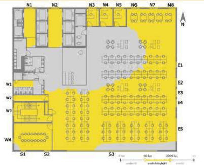
If the whole building performance approach is used, compliance for daylighting requirements can be checked by analysing the façade and floor plate design in an analytical software approved by BEE (3.4). The image below, developed through an approved software, specifies the lux levels and time-period of a year during which lighting levels would be available. With this information, designers can check if the required minimum area as per 4.2.3 has the required daylight levels
UDI Analysis with a Daylighting Analysis Software
(b) Manual calculation method
For projects adopting the prescriptive compliance approach, manual calculation method can be used for UDI compliance.
From Table 4-3 determine the daylight extent factor (DEF) for each orientation. For a building located in Delhi (latitude > 15 degrees), with glazing of VLT ≥ 0.39, shading PF ≥0.4 and light shelves in windows, DEFs for windows in North = 3.5, in South = 3.0, in East = 2.1, and in West = 1.8. Head height is 3.0 m.
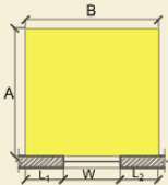
For fenestration clear of any opaque obstructions calculate daylit floor area (AxB).
A: In the direction perpendicular to the fenestration, daylit area extends to head height of the fenestration multiplied by the daylight extent factor (DEF) or distance till an opaque partition higher than head height of the fenestration, whichever is less.
B: In the direction parallel to the fenestration daylit area extends a horizontal dimension equal to the width of the fenestration plus either one meter on each side of the aperture or the distance to an opaque partition, or one-half the distance to an adjacent fenestration, whichever is least.
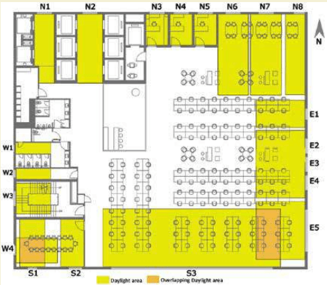
For overlapping daylit areas such as corner windows. Subtract the overlapping daylit area from the sum of daylit area.
UDI Analysis with manual calculations
As per the calculations 616.5 m2 of floor area will meet the UDI requirements during 90% of the year. This is 49.2 % of the total above grade floor area of 1,254 m2. Thus, the building floor will comply with UDI requirement. Following Tables shows calculated Daylight Area Meeting UDI Requirement.
Table 4-1-1Manual calculation for Daylight Area Meeting UDI Requirement
Orientation-NORTH, DEF-3.5, Fenestration Head Height H - 3m
Window without opaque obstructions
Fenestration Width W (m)
A= H x DEF (m)
B = L₁ + W + L₂ (m) L₁ = L₂ = 1m
Area meeting the UDI requirements = AxB (m²)
N7
2.0
10.5
4.0
42.0
4.3.3Vertical Fenestration
For all climatic zones, vertical fenestration compliance requirements for all three energy efficiency levels, i.e. ECBC, ECBC+, and Super ECBC, shall comply with the following:
(a) Maximum allowable Window Wall Ratio (WWR) is 40% (applicable to buildings showing compliance using the Prescriptive Method, including Building Envelope Trade-off Method)
(b) Minimum allowable Visible light transmittance (VLT) is 0.27
(c) Assembly U-factor shall be determined for the overall fenestration product (including the sash and frame)
Vertical fenestration shall comply with the maximum Solar Heat Gain Coefficient (SHGC) and U-factor requirements of Table 4-10 for ECBC buildings and Table 4-11 for ECBC+ buildings and Super ECBC buildings. Vertical fenestration on non-cardinal direction, shall be categorized under a particular cardinal direction if its orientation is within ±45°of that cardinal direction.
Table 4-10Vertical Fenestration Assembly U-factor and SHGC Requirements for ECBC Buildings
Composite
Hot and dry
Warm and humid
Temperate
Cold
Maximum U-factor (W/m².K)
3.00
3.00
3.00
3.00
3.00
Maximum SHGC Non-North
0.27
0.27
0.27
0.27
0.62
Maximum SHGC North for
0.50
0.50
0.50
0.50
0.62
latitude ≥ 15°N
Maximum SHGC North for
0.27
0.27
0.27
0.27
0.62
latitude < 15°N
See Appendix A for default values
of unrated fenestration.
Table 4-11Vertical Fenestration U-factor and SHGC Requirements for ECBC+ buildings and Super ECBC buildings
Composite
Hot and dry
Warm and humid
Temperate
Cold
Maximum U-factor (W/m2.K)
2.20
2.20
2.20
3.00
1.80
Maximum SHGC Non-North
0.25
0.25
0.25
0.25
0.62
Maximum SHGC North for latitude ≥ 15°N
0.50
0.50
0.50
0.50
0.62
Maximum SHGC North for latitude < 15°N
0.25
0.25
0.25
0.25
0.62
Exceptions to SHGC requirements in Table 4-10 and Table 4-11:
(a) For fenestration with a permanent external projection, including but not limited to overhangs, side fins, box frame, verandah, balcony, and fixed canopies that provide permanent shading tothe fenestration, thee quivalent SHGC for the proposed shaded fenestration may be determined as less than or equal to the SHGC requirements of Table 4-10 and Table 4-11. Equivalent SHGC shall be calculated by following the steps listed below:
Projection factor (PF) for the external permanent projection, shall be calculated as per the applicable shading type listed in §8.2. The range of projection factor for using the SEF is 0.25≤PF≤1.0 The SEF is applicable for both side fins shading only other than overhangs. The projection factor shall be calculated for both side fins and the lower projection factor of each fin shall be considered. Other shading devices shall be modeled through the Whole Building Performance Method in §9.
ii. A shaded vertical fenestration on a non-cardinal direction, shall be categorized either under a particular cardinal direction or a primary inter-cardinal direction if its orientation is within the range of ±22.5 degrees of the cardinal or primary inter-cardinal direction.
iii. Any surrounding man-made or natural sunlight obstructers shall be considered as a permanent shading of PF equal to 0.4 if
a. the distance between the vertical fenestration of the building, for which compliance is shown, and surrounding man-made or natural sunlight obstructers is less than or equal to twice the height of the surrounding man-made or natural sunlight obstructers; and
b. the surrounding man-made or natural sunlight obstructers shade the façade for at least 80% of the total time that the façade is exposed to direct sun light on a summer solstice. Compliance shall be shown using a sun path analysis for summer solstice for the vertical fenestration.
iv. An equivalent SHGC is calculated by dividing the SHGC of the unshaded fenestration product with a Shading Equivalent Factor (SEF). SEF shall be determined for each orientation and shading device typefrom Table 4-10 and Table 4-11.
v. The maximum allowable SHGC is calculated by multiplying the prescriptive SHGC requirement for respective compliance level from Table 4-10 and Table 4-11 with the SEF.
ENVELOPE
ENVELOPE
Table 4-12Shading Equivalent Factors for Latitudes greater than or equal to 1 5 o N
Shading Equivalent Factors (SEF) for latitudes greater than or equal to 15˚N
Shading Equivalent Factors (SEF) for latitudes greater than or equal to 15˚N
Shading Equivalent Factors (SEF) for latitudes greater than or equal to 15˚N
Shading Equivalent Factors (SEF) for latitudes greater than or equal to 15˚N
Shading Equivalent Factors (SEF) for latitudes greater than or equal to 15˚N
Shading Equivalent Factors (SEF) for latitudes greater than or equal to 15˚N
Shading Equivalent Factors (SEF) for latitudes greater than or equal to 15˚N
Shading Equivalent Factors (SEF) for latitudes greater than or equal to 15˚N
Shading Equivalent Factors (SEF) for latitudes greater than or equal to 15˚N
Shading Equivalent Factors (SEF) for latitudes greater than or equal to 15˚N
SFE
FP
hNtro
Etsa
hStou
Wtse
hNtro- Etsa
hStou- Etsa
hStou- Wtse
hNtro- Wtse
i Fsn +g hnar Oev
0.25
1.25
1.37
1.58
1.36
1.47
1.47
1.42
1.53
i Fsn +g hnar Oev
0.3
1.29
1.48
1.72
1.43
1.54
1.65
1.57
1.58
i Fsn +g hnar Oev
0.35
1.34
1.58
1.88
1.51
1.62
1.81
1.73
1.65
i Fsn +g hnar Oev
0.4
1.39
1.67
2.06
1.61
1.70
1.97
1.89
1.75
i Fsn +g hnar Oev
0.45
1.43
1.76
2.26
1.71
1.78
2.11
2.06
1.87
i Fsn +g hnar Oev
0.5
1.47
1.85
2.47
1.83
1.86
2.25
2.23
2.00
i Fsn +g hnar Oev
0.55
1.51
1.94
2.69
1.96
1.94
2.38
2.40
2.13
i Fsn +g hnar Oev
0.6
1.55
2.03
2.92
2.09
2.02
2.51
2.58
Table 4-13Shading Equivalent Factors for Latitudes less than 15 ºN
Shading Equivalent Factors (SEF) for latitudes less than 15˚N
SFE
FP
hNtro
Etsa
hStou
Wtse
hNtro- Etsa
hStou- Etsa
hStou- Wtse
hNtro- Wtse
i Fsn +g hnar Oev
0.25
1.38
1.33
1.30
1.34
1.42
1.41
1.37
1.42
0.3
1.44
1.42
1.35
1.42
1.49
1.46
1.41
1.52
0.35
1.50
1.50
1.42
1.50
1.57
1.52
1.47
1.63
0.4
1.56
1.59
1.50
1.59
1.66
1.59
1.54
1.73
0.45
1.61
1.67
1.59
1.69
1.76
1.67
1.61
1.84
0.5
1.67
1.76
1.68
1.80
1.87
1.75
1.70
1.94
0.55
1.72
1.85
1.79
1.90
1.98
1.85
1.80
2.05
0.6
1.77
1.94
1.89
2.02
2.09
1.94
1.89
2.15
0.65
1.82
2.02
1.99
2.13
2.20
2.04
2.00
2.25
0.7
1.86
2.11
2.08
2.24
2.31
2.15
2.10
2.36
0.75
1.90
2.19
2.17
2.35
2.42
2.25
2.21
2.46
0.8
1.94
2.28
2.25
2.46
2.53
2.35
2.31
2.55
0.85
1.98
2.36
2.31
2.56
ENVELOPE
ENVELOPE
Shading Equivalent Factors (SEF) for latitudes less than 15˚N
hnagrev O
0.25
1.15
1.19
1.09
1.20
1.17
1.08
1.04
1.18
0.3
1.17
1.23
1.07
1.24
1.22
1.12
1.08
1.21
0.35
1.20
1.28
1.07
1.29
1.26
1.16
1.12
1.25
0.4
1.22
1.32
1.07
1.33
1.30
1.19
1.17
1.29
0.45
1.24
1.37
1.09
1.38
1.33
1.23
1.21
1.32
0.5
1.26
1.42
1.12
1.42
1.37
1.28
1.25
1.35
0.55
1.28
1.46
1.15
1.46
1.40
1.32
1.29
1.39
0.6
1.30
1.51
1.18
1.50
1.43
1.36
1.33
1.42
0.65
1.32
1.55
1.22
1.55
1.46
1.40
1.37
1.45
0.7
1.33
1.60
1.26
1.59
1.48
1.43
1.40
1.48
0.75
1.35
1.64
1.29
1.62
1.51
1.47
1.44
1.50
0.8
1.37
1.67
1.32
1.66
1.53
1.51
1.47
1.53
0.85
1.38
1.71
1.35
1.70
1.55
1.54
1.51
1.56
0.9
1.39
1.74
1.37
1.73
1.57
1.56
1.54
1.58
0.95
1.40
1.77
1.38
1.77
1.59
1.59
1.56
1.61
≥1
1.41
1.79
Vertical fenestration, located such that its bottom is more than 2.2 m above the level of the floor, is exempt from the SHGC requirements in Table 4-10 and Table 4-11, if the following conditions are complied with:
i. The Total Effective Aperture (WWR X VLT) for the elevation is less than 0.25, including all fenestration areas more than 1.0 meter above the floor level; and,
ii. An interior light shelf is provided at the bottom of this fenestration area, with a projection factor on interior side not less than:
a. 1.0 for E-W, SE, SW, NE, and NW orientations
b. 0.50 for S orientation, and
c. 0.35 for N orientation when latitude is less than 15°N.
ENVELOPE
Note 4-1 Equivalent SHGC and Projection Factor
A 5,400 m2 two story office building in Delhi is trying to achieve ECBC level compliance. It has a rectangular layout (90 m x 30 m) with floor to floor height of 4.0 m and floor area is evenly distributed over the two floors. Windows are either east or west facing and equally distributed on the two floors. The windows are all 1.85m in length and 2.165m in height with an overhang of 0.85 m, sill level is 1.385m above floor level. The overall glazing area is 384 m2. SHGC of the glazing in the East/West Fenestration is 0.30; area weighted U-Factor is 3.0 W/m2.K.VLT of the glazing in all
orientation is 0.5. Will the vertical fenestration comply with the ECBC through prescriptive approach?
iv. Glazed façades, with non-cardinal orientation, shall be categorized under a particular cardinal direction if its orientation is within ± 45 degrees of that cardinal direction.
v. Daylit area overlap: For overlapping daylit areas such as windows on different orientations or in case of skylights the overlapping daylit area shall be subtracted from the sum of daylit area.
Documentation requirement:
vi. A separate architectural plan shall be prepared with all daylit areas marked on the floor plans.
vii. A summary shall be provided showing compliance as per Table 4-1.
N6
2.0
10.5
4.0
42.0
N2
2.0
10.5
4.0
42.0
Window with opaque obstructions
Fenestration Width W (m)
A= Distance till parallel Obstruction (m)
B = L₁ + W + L₂ (m) L₁ = L₂ = Distance to perpendicular Obstructions
Area meeting the UDI requirements = AxB (m²)
N1
2.0
10.5
0.3+2+0.3=2.6
27.3
N3
2.0.
4.0
0.4+2+0.4=2.8
11.2
N4
2.0
4.0
0.4+2+0.4=2.8
11.2
N5
2.0
4.0
0.4+2+0.4=2.8
11.2
N8
1.5
10.5
0+1.5+1.0=2.5
26.3
Daylit area meeting UDI requirement
213.2
Orientation-SOUTH, DEF-3, Fenestration Head Height H - 3m
Window without opaque obstructions
Fenestration Width W (m)
A= H x DEF (m)
B= L₁ +W+ L₂ (m) L₁ = L₂ =1m
Area meeting the UDI requirements = AxB( m² )
S1
1.2
6.2
1.0+1.2+1.0=3.3
20.1
S2
1.7
6.2
1.0+1.7+0.3=3.0
18.6
S3
21.0
9.0
1.0+21.0+1.0=24
216.0
Daylit area meeting UDI requirement
254.7
Orientation-EAST, DEF-2.1, Fenestration Head Height H - 3m
Window without opaque obstructions
Fenestration Width W (m)
A= H x DEF (m)
B = L₁ + W + L₂( m) L₁ = L₂ = 1m
Area meeting the UDI requirements = AxB(m²)
E1
1.5
6.3
1.0 + 1.5 + 1.0 = 3.5
22.1
E5
5.5
6.3
1.0 + 5.5 + 1.0 = 7.5
47.3
Adjacent fenestration less than two meter apart
Fenestration Width W (m)
A= H x DEF (m)
B = L₁ + W + L₂( m) L₁,L₂ = one half of distance to adjacent fenestration
Area meeting the UDI requirements = AxB(m²)
E2
2
6.3
1.0 + 2.0 + 0.2 = 3.2
20.2
E3
2
6.3
0.2 + 2 + 0.2 = 2.4
15.1
E4
2
6.3
0.2 + 2 + 1 = 3.2
20.2
Daylit area meeting UDI requirement
124.9
Orientation-WEST, DEF-1.8, Fenestration Head Height H - 3m
Window without opaque obstructions
Fenestration Width W (m)
A= H x DEF (m)
B = L₁ + W + L₂ (m) L₁ = L₂ = 1m
Area meeting the UDI requirements = AxB (m²)
W3
2.0
5.4
1.0+2.0+1.0=4.0
21.6
W4
1.4
5.4
1.0+1.2+1.0=3.2
17.3
Window with opaque obstructions in daylit area
Fenestration Width W (m)
A= H x DEF (m)
B = L₁ + W + L₂ (m) L₁ = L₂ = Distance to perpendicular Obstructions
Area meeting the UDI requirements = AxB (m²)
W1
1.0
5.4
0.3+1+0.3=1.6
8.6
W2
1.0
5.4
0.3+1+0.3=1.6
8.6
Daylit area meeting UDI requirement
56.1
Overlapping area calculations
Window with overlap areas
Width (m)
Depth (m)
Area ( m² )
N4 and S1
3.3
3.3
10.9
S3 and E5
3.3
6.5
21.5
Overlapping daylight area (b)
32.4
Total Daylit area
ORIENTATION
Daylit area (m2)
NORTH
213.2
SOUTH
254.7
EAST
124.9
WEST
56.1
Total daylight area (a)
648.9
Total Overlapping daylit area (b)
32.4
Total daylit area meeting UDI requirement during 90% of the year (a-b)
616.5
ENVELOPE
2.27
i Fsn +g hnar Oev
0.65
1.59
2.13
3.15
2.24
2.10
2.64
2.76
2.40
i Fsn +g hnar Oev
0.7
1.63
2.24
3.18
2.39
2.18
2.77
2.94
2.53
i Fsn +g hnar Oev
0.75
1.66
2.37
3.19
2.56
2.25
2.90
3.12
2.64
i Fsn +g hnar Oev
0.8
1.70
2.52
3.20
2.72
2.33
3.04
3.18
2.73
i Fsn +g hnar Oev
0.85
1.73
2.69
3.21
2.90
2.40
3.11
3.23
2.80
i Fsn +g hnar Oev
0.9
1.76
2.89
3.24
3.07
2.46
3.15
3.25
2.84
i Fsn +g hnar Oev
0.95
1.79
3.11
3.28
3.25
2.52
3.17
3.27
2.85
i Fsn +g hnar Oev
≥1
1.80
3.30
3.33
3.33
2.57
3.23
3.30
2.82
hnag rev O
0.25
1.09
1.21
1.28
1.20
1.17
1.26
1.23
1.20
hnag rev O
0.3
1.11
1.26
1.34
1.27
1.22
1.32
1.27
1.24
hnag rev O
0.35
1.13
1.30
1.39
1.33
1.26
1.39
1.32
1.28
hnag rev O
0.4
1.15
1.35
1.46
1.38
1.30
1.46
1.38
1.32
hnag rev O
0.45
1.16
1.40
1.52
1.43
1.33
1.53
1.46
1.36
hnag rev O
0.5
1.18
1.45
1.59
1.48
1.35
1.60
1.54
1.40
hnag rev O
0.55
1.20
1.51
1.66
1.52
1.38
1.67
1.62
1.44
hnag rev O
0.6
1.21
1.56
1.73
1.57
1.40
1.74
1.70
1.47
hnag rev O
0.65
1.22
1.62
1.81
1.61
1.42
1.81
1.79
1.51
hnag rev O
0.7
1.24
1.68
1.88
1.66
1.45
1.88
1.87
1.55
hnag rev O
0.75
1.25
1.74
1.95
1.72
1.48
1.94
1.94
1.58
hnag rev O
0.8
1.26
1.80
2.02
1.77
1.51
2.00
2.01
1.61
hnag rev O
0.85
1.27
1.86
2.09
1.84
1.56
2.06
2.06
1.64
hnag rev O
0.9
1.28
1.92
2.15
1.91
1.61
2.11
2.10
1.67
hnag rev O
0.95
1.29
1.99
2.21
1.98
1.67
2.15
2.13
1.70
hnag rev O
≥1
1.30
2.06
2.26
2.07
1.75
2.19
2.14
1.72
Shading Equivalent Factors (SEF) for latitudes greater than or equal to 15˚N
Shading Equivalent Factors (SEF) for latitudes greater than or equal to 15˚N
Shading Equivalent Factors (SEF) for latitudes greater than or equal to 15˚N
Shading Equivalent Factors (SEF) for latitudes greater than or equal to 15˚N
Shading Equivalent Factors (SEF) for latitudes greater than or equal to 15˚N
Shading Equivalent Factors (SEF) for latitudes greater than or equal to 15˚N
Shading Equivalent Factors (SEF) for latitudes greater than or equal to 15˚N
Shading Equivalent Factors (SEF) for latitudes greater than or equal to 15˚N
Shading Equivalent Factors (SEF) for latitudes greater than or equal to 15˚N
Shading Equivalent Factors (SEF) for latitudes greater than or equal to 15˚N